Fast iterative shrinkage beam-forming sound source identification method

A technology of iterative contraction and sound source identification, applied in radio wave measurement systems, instruments, complex mathematical operations, etc., can solve the problems of limited practical application, slow convergence speed, long calculation time, etc., and achieve better comprehensive performance of sound source identification , fast convergence, and reduced computation

Active Publication Date: 2019-02-15
CHONGQING UNIV
View PDF5 Cites 7 Cited by
  • Summary
  • Abstract
  • Description
  • Claims
  • Application Information

AI Technical Summary

Problems solved by technology

Common methods include DAMAS, NNLS, Richardson-Lucy, etc. However, the above methods have problems such as long calculation time and slow convergence speed, which limit their practical application.

Method used


Image

  • Fast iterative shrinkage beam-forming sound source identification method
  • Fast iterative shrinkage beam-forming sound source identification method
  • Fast iterative shrinkage beam-forming sound source identification method

Examples


Embodiment Construction

[0037] Below in conjunction with accompanying drawing and embodiment the present invention will be further described:

[0038] The present invention comprises the following steps:

[0039] Step 1. Construct difference function

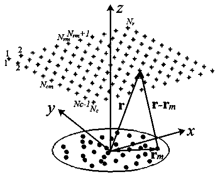
[0040] figure 1 It is a schematic diagram of beamforming sound source identification layout, where r is the focusing coordinate vector, and r m (m=1,2,3,...,M) is the coordinate vector of the mth microphone, M is the number of microphones, N r and N c Respectively, the number of rows and columns of grid points, N rm and N cm are the number of rows and columns where the central grid point is located, respectively.

[0041] The cross-spectrum imaging function is a common algorithm for beamforming. It assumes a monopole sound source distribution model at the focus grid point position, and minimizes the difference between the acoustic signal cross-spectrum generated by the model point sound source and the actual measured acoustic signal cross-spectru...


PUM


Abstract

The invention discloses a fast iterative shrinkage beam-forming sound source identification method, which comprises the following steps: S1, constructing a difference function; S2, calculating the minimum result error after Fourier transformation of Aq-b, and converting the non-negative least squares problem in the difference function into a minimization formula based on Fourier transformation; and S3, iteratively calculating Q, wherein Q is the distribution vector of a sound source after Fourier transformation. Compared with the existing sound source identification method, the fast iterativeshrinkage beam-forming sound source identification method of the invention has higher calculation efficiency, better convergence, faster convergence and better comprehensive performance of sound source identification.

Description

technical field [0001] The invention belongs to the technical field of sound field recognition. Background technique [0002] The deconvolution-based beamforming clear algorithm can effectively improve the spatial resolution of traditional beamforming, suppress sidelobe ghosts, and improve the performance of sound source identification. The core idea of ​​this type of method is based on the fact that the output of traditional beamforming can be approximated to the convolution of the sound source distribution and the array point spread function, and the real information of the sound source can be obtained through deconvolution. Common methods include DAMAS, NNLS, Richardson-Lucy, etc. However, the above methods have problems such as long calculation time and slow convergence speed, which limit their practical application. In order to overcome the above problems, on the basis of assuming that the spatial transfer of the array point propagation function is unchanged, based on ...

Claims


Application Information

Patent Timeline
Patent Type & Authority Applications(China)
IPC IPC(8): G01S5/18G06F17/14
CPCG06F17/141G01S5/18
Inventor 褚志刚周其祥沈林邦吴桂娇杨洋
Owner CHONGQING UNIV
Why Eureka
Try Eureka