Supercharge Your Innovation With Domain-Expert AI Agents!

Motor rotor structure and permanent magnet motor

A motor rotor and rotor technology, applied in the direction of magnetic circuit shape/style/structure, magnetic circuit, synchronous machine, etc., can solve the problems of reduced motor efficiency, limited speed range, and increased copper loss of the motor

Pending Publication Date: 2019-02-15
GREE ELECTRIC APPLIANCES INC
View PDF0 Cites 7 Cited by
  • Summary
  • Abstract
  • Description
  • Claims
  • Application Information

AI Technical Summary

Problems solved by technology

[0003] Based on this, it is necessary to provide a motor rotor structure and a permanent magnet motor for the problems of increased copper loss, reduced motor efficiency, and limited speed range when the traditional permanent magnet motor expands its operating range through field-weakening control.

Method used


Image

  • Motor rotor structure and permanent magnet motor
  • Motor rotor structure and permanent magnet motor
  • Motor rotor structure and permanent magnet motor

Examples


Embodiment Construction

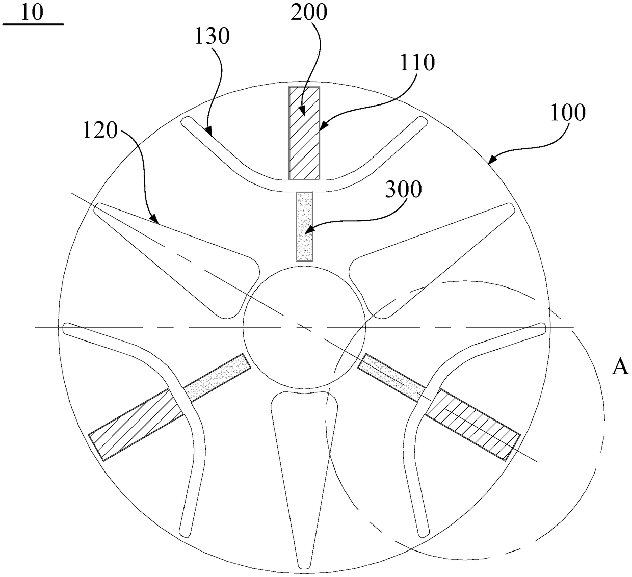
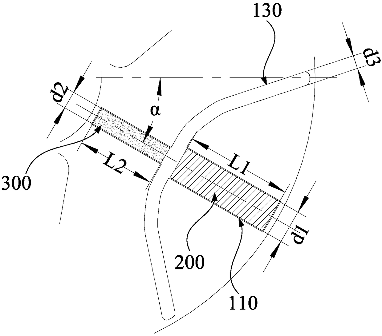
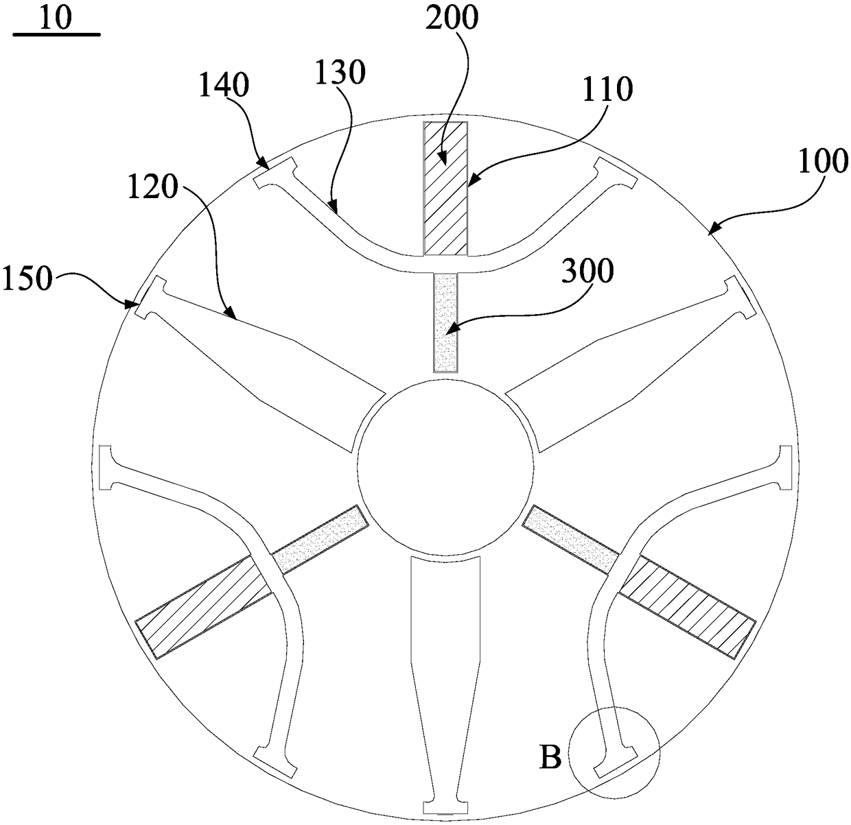
[0035] In order to make the purpose, technical solution and advantages of the present invention clearer, the motor rotor structure and the permanent magnet motor of the present invention will be further described in detail through the following embodiments in conjunction with the accompanying drawings. It should be understood that the specific embodiments described here are only used to explain the present invention, not to limit the present invention.

[0036] It should be noted that when an element is referred to as being “fixed” to another element, it can be directly on the other element or there can also be an intervening element. When an element is referred to as being "connected to" another element, it can be directly connected to the other element or intervening elements may also be present. In contrast, when an element is referred to as being "directly on" another element, there are no intervening elements present. The terms "vertical," "horizontal," "left," "right," ...


PUM


Abstract

The invention relates to the technical field of motors, in particular to a motor rotor structure. The motor rotor structure comprises a rotor iron core; a plurality of radial grooves are formed in a circumferential direction; a first magnetic isolation groove is formed between the two adjacent radial grooves; two permanent magnets with different coercive forces are installed in each radial groove;the two permanent magnets with the different coercive forces are distributed in a radial direction of the rotor iron core; the two permanent magnets with the different coercive forces are magnetizedin a tangential direction of the rotor iron core; a second magnetic isolation groove is formed between the two permanent magnets with the different coercive forces; when magnetization directions of the two permanent magnets with the different coercive forces are opposite, the rotor iron core is in a multi-magnetic-pole state; and when the magnetization directions of the two permanent magnets withthe different coercive forces are same, the rotor iron core is in a few-magnetic-pole state. The motor rotor structure can adjust an internal magnetic field according to an operating condition of a motor, so that the rotor iron core comprises the multi-magnetic-pole state and the few-magnetic-pole state, an efficient area of the motor is expanded, and the operation range of the motor is expanded.

Description

technical field [0001] The invention relates to the technical field of motors, in particular to a motor rotor structure and a permanent magnet motor. Background technique [0002] The permanent magnet synchronous motor with adjustable magnetic flux can adjust the strength of the internal magnetic field of the motor according to the load condition of the motor. Traditional permanent magnet motors rely on permanent magnets to provide magnetic flux, but permanent magnets provide a fixed magnetic field, and the internal magnetic field of the motor is difficult to adjust, making it difficult for permanent magnet motors to take into account the efficiency at high and low frequencies. And in the case of a fixed power supply voltage, the maximum operating frequency of the motor is limited. At present, most permanent magnet motors can only expand the operating range through field-weakening control, but field-weakening control has problems such as increasing the copper loss of the mo...

Claims


Application Information

Patent Timeline
IPC IPC(8): H02K1/27
CPCH02K1/2753H02K2213/03H02K1/276H02K1/246H02K21/046H02K2213/09H02K1/26H02K21/10H02K1/27
Inventor 王敏肖勇李权锋
Owner GREE ELECTRIC APPLIANCES INC
Features
  • R&D
  • Intellectual Property
  • Life Sciences
  • Materials
  • Tech Scout
  • Unparalleled Data Quality
  • Higher Quality Content
  • 60% Fewer Hallucinations
Learn More