Flying target detection interference system and method

A technology of flight target and jamming system, applied in the field of radio jamming technology, can solve the problems of lost jamming target, low system efficiency, rising cost, etc., and achieve the effect of eliminating flight safety and the danger of leaking secrets

Pending Publication Date: 2019-02-15
BEIJING SHIAN LITIAN TECH DEV CO LTD
View PDF10 Cites 7 Cited by
  • Summary
  • Abstract
  • Description
  • Claims
  • Application Information

AI Technical Summary

Problems solved by technology

Most of these methods or systems have inefficiencies
In particular, the detection and interference range of existing radio interference equipment is limited by its maximum detection and emission angle range. Therefore, it is not possible to scan and interfere with the entire airspace in all directions
In order to conduct a full-range scan, multiple jamming devices need to be deployed for different airspace segments, which will lead to a sharp increase in cost
Moreover, once the flying target flies out of the jamming range of one of them, the jamming target will be lost, making continuous jamming impossible

Method used


Image

  • Flying target detection interference system and method
  • Flying target detection interference system and method
  • Flying target detection interference system and method

Examples


Embodiment Construction

[0020] Reference will now be made in detail to the exemplary embodiments, examples of which are illustrated in the accompanying drawings. When the following description refers to the accompanying drawings, the same numerals in different drawings refer to the same or similar elements unless otherwise indicated. The implementations described in the following exemplary examples do not represent all implementations consistent with the present disclosure. Rather, they are merely examples of apparatuses and methods consistent with aspects of the present disclosure as recited in the appended claims.

[0021] The terminology used in the present disclosure is for the purpose of describing particular embodiments only, and is not intended to limit the present disclosure. As used in this disclosure and the appended claims, the singular forms "a", "the", and "the" are intended to include the plural forms as well, unless the context clearly dictates otherwise. It should also be understood...


PUM


Abstract

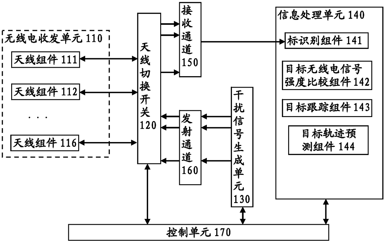
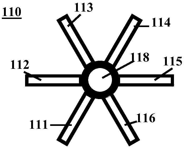
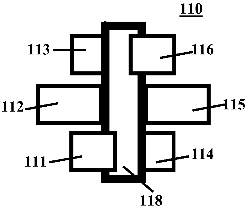
The invention relates to a flying target detection interference system and method. The system comprises a radio transceiver unit, a signal processing unit, an interference signal generation unit and acontrol unit. The radio transceiver unit is used for receiving a target radio signal transmitted by a flying target or transmitting a radio interference signal to the flying target in a specific airspace. The signal processing unit is used to receive and process the target radio signal from one of radio antenna assemblies, and determine a serial number of the radio antenna assembly closest to theflying target. The interference signal generation unit generates a radio interference signal and transmits the radio interference signal to one of the radio antenna assemblies for performing transmission. The control unit controls the radio antenna assembly corresponding to the serial number to receive the radio interference signal generated by the interference signal generation unit and transmitthe radio interference signal to the flying target.

Description

technical field [0001] The present disclosure relates to a radio jamming technology, in particular to a radio detection jamming system and method for flying targets. Background technique [0002] With the rapid development of various drones from the field of children's toys to the civilian field of drones, the illegal use of drones frequently occurs, and its harm to flight safety is becoming more and more serious. Moreover, due to the convenience of using drones, it is easier to leak secrets in airspace or areas that require security and confidentiality. In order to effectively respond to the needs of flight safety and information confidentiality, it is particularly important to conduct, interfere, control and capture UAVs in a certain airspace. [0003] The existing UAV jamming equipment mostly uses shooting down, UAV capture, radio trapping and radio jamming equipment for radio jamming. Most of these methods or systems are inefficient. In particular, the detection and i...

Claims


Application Information

Patent Timeline
Patent Type & Authority Applications(China)
IPC IPC(8): H04K3/00
CPCH04K3/825
Inventor 李波辛正大何冠男韦震孙旭王禹杨争斌
Owner BEIJING SHIAN LITIAN TECH DEV CO LTD
Why Eureka
Try Eureka