Method and fixture for controlling welding deformation of igniter

A welding deformation and control point technology, applied in welding equipment, manufacturing tools, welding equipment, etc., can solve the problems of insecure size, engine failure, wall thickness out of tolerance, etc. Reliability, effect of controlling welding deformation

Active Publication Date: 2020-05-26
CHINA HANGFA GUIZHOU LIYANG AVIATION POWER CO LTD
View PDF5 Cites 0 Cited by
  • Summary
  • Abstract
  • Description
  • Claims
  • Application Information

AI Technical Summary

Problems solved by technology

The fixture configured in this process plan, the step pins A4 and A6 only have positioning function, but no clamping function, and the distance between the parts and the clamp is limited, and the welding torch cannot be inserted into the welding, so the fixture only has the function of positioning welding, not welding. , that is, the parts are first positioned on the fixture for welding, and the welding must be removed and welded in a free state. The welding deformation is not controlled, resulting in the position and size of the two joints of the boss 4 not being guaranteed, so that when the joint is machined later, the wall thickness is out of tolerance, or even The problem of "gap" causes the product to be scrapped; in addition, the welding seam of this process method is in a vertical position, and the welding tumor in the inner cavity of the component is difficult to control. If the tumor is combined with the main body of the part, if it is not strong enough, the engine will vibrate violently when it is working. Cause the tumor to fall off, form redundant matter, and cause the engine to fail

Method used


Image

  • Method and fixture for controlling welding deformation of igniter
  • Method and fixture for controlling welding deformation of igniter
  • Method and fixture for controlling welding deformation of igniter

Examples


Embodiment Construction

[0026] The method and jig for controlling the welding deformation of the igniter according to the present invention will be described in detail below in conjunction with the accompanying drawings.

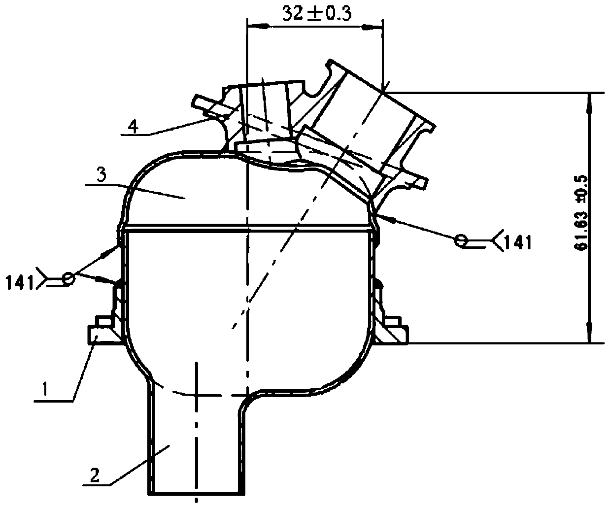
[0027] figure 1 The aero-engine igniter assembly is shown, and the assembly is formed by welding the mounting edge 1, the lower shell 2, the upper shell 3, and the boss 4. After welding, the inner cavity of the two joints of the mounting edge 1 and the boss 4 are machined. The boss 4 has two joints, a large joint and a small joint; during the welding of the original process, the size of the large joint of the boss is Φ18mm * 30mm, and the small joint Φ8mm * 18mm. The welding of the igniter requires that the size of the large joint joint of the boss be ensured, the height direction is 61.63mm±0.5mm, the length direction is 32mm±0.3mm, and the width direction is located on the center plane of the installation side. Now, using the method of the present invention, the method and jig f...


PUM

PropertyMeasurementUnit
verticalityaaaaaaaaaa

Abstract

The invention discloses a method and fixture for controlling welding deformation of an igniter. A technological threaded hole used for clamping is added in a large joint inner cavity of a boss of theigniter, a hole is designed in the middle part of a traditional positioning bolt, then, the boss is tensioned by employing a screw, so that the boss is fixed onto the bolt, and then, the boss not onlyis positioned but also is clamped; a square hole is formed in a suitable position of a fixture body corresponding to a welding seam, so that a welding gun is prevented from interfering with the fixture body, and an assembly is welded under a rigid constraint state; and a part welding way is changed, i.e., a part is changed into a vertical state from a horizontal state, so that the phenomenon thata welding pool of the welding seam sags due to self gravity to form excrescences making connection unreliable in the inner cavity is avoided.

Description

technical field [0001] The invention relates to the field of welding technology, in particular to a method and a fixture for controlling the welding deformation of an aero-engine igniter. Background technique [0002] Such as figure 1 The aero-engine igniter assembly is shown. The assembly is formed by welding the mounting side 1, the lower shell 2, the upper shell 3, and the boss 4. After welding, the inner cavity and the end surface of the two joints of the mounting edge 1 and the boss 4 are machined. Wait. The lower shell 2 and the upper shell 3 are butt-buttoned (the branch is matched with the limit) to form a closed inner cavity of the ignition generator. The inner cavity of the ignition generator is assembled in the "waist-shaped" inner hole of the installation side 1, along the "waist "Type" hole edge welding, so that the ignition generator inner cavity and the installation edge form a permanent connection; the upper end of the ignition generator is provided with a ...

Claims


Application Information

Patent Timeline
Patent Type & Authority Patents(China)
IPC IPC(8): B23K37/04B23K31/02
CPCB23K31/003B23K31/02B23K37/0443
Inventor 熊健李鸿平金汝飞冷滨游晓君陈朱鹰何鹏
Owner CHINA HANGFA GUIZHOU LIYANG AVIATION POWER CO LTD
Why Eureka
Try Eureka