Machining device for large-caliber optic free curved surface

A surface processing, large-diameter technology, applied in optical surface grinders, automatic grinding control devices, metal processing equipment, etc., can solve the problems of low processing efficiency, poor load capacity, slow dynamic response speed, etc., to overcome the processing stiffness. Insufficiency, improvement of the limited processing range, and the effect of increasing the machinable angle

Inactive Publication Date: 2019-02-19
SHANDONG ZHONGHENG OPTOELECTRONIC TECH CO LTD
View PDF7 Cites 5 Cited by
  • Summary
  • Abstract
  • Description
  • Claims
  • Application Information

AI Technical Summary

Problems solved by technology

However, due to the requirement of high rigidity of the equipment in the mirror processing process, the mechanical arm is often relatively heavy. Among them, the tandem processing machine tool has problems such as low rigidity, slow dynamic response speed, low precision caused by accumulated errors, and poor load capacity; while the parallel processing machine tool is due to rotation. The small angle leads to a limited processing range of optical free-form surfaces. For the processing of large-scale optical free-form surfaces, a gantry-type processing mechanism is required to expand the processing range of the surface, especially for some complex optical free-form surfaces such as high-order surfaces, sinusoidal surfac

Method used


Image

  • Machining device for large-caliber optic free curved surface
  • Machining device for large-caliber optic free curved surface
  • Machining device for large-caliber optic free curved surface

Examples


Embodiment Construction

[0020] The present invention will be described in detail below in conjunction with the accompanying drawings and specific embodiments.

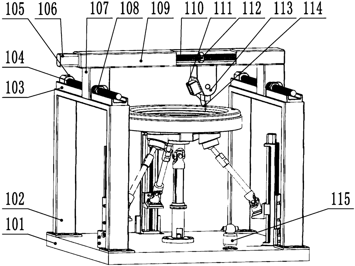
[0021] Such as figure 1 and figure 2As shown, a large-diameter optical free-form surface processing device includes a processing unit, an optical free-form surface support unit, and an optical free-form surface clamping unit; the processing unit is installed on the upper end of the processing support seat, and the processing support seat includes a base 101 and is fixed on the base The support frame 102 at both ends of 101; the processing unit includes a processing tool 114 and a driving mechanism that provides a processing path for the processing tool 114. The driving mechanism includes an X-direction driving mechanism and a Y-direction driving mechanism, and the Y-direction driving mechanism is two groups of parallel arrangements. Lead screw nut drive mechanism, including Y direction lead screw support seat 103 fixed on two supporting fra...


PUM


Abstract

The invention discloses a machining device for the large-caliber optic free curved surface. The machining device comprises a machining unit, an optic free curved surface supporting unit and an optic free curved surface clamping unit. The machining unit comprises a machining cutter and a drive mechanism for providing a machining path for the machining cutter. The drive mechanism comprises an X-direction drive mechanism and a Y-direction drive mechanism. The optic free curved surface supporting unit comprises a 3HUS+PU parallel mechanism, a moving platform connected to the upper end of the 3HUS+PU parallel mechanism and three sets of linear modules. The parallel mechanism drives the moving platform to move in the vertical direction to machine the curved surface, then the parallel mechanism rotates around the X-axis direction and the Y-axis direction, and then the posture of the free curved surface to be machined can be further adjusted. While the machining precision is ensured, the machining angle of the free curved surface can be increased. The machining device is high in overall equipment rigidity, small in accumulative error, high in machining precision and large in machining range, the optic free curved surface with the high complex degree can be machined, control is easy, and the machining efficiency is improved effectively.

Description

technical field [0001] The invention relates to an optical free-form surface processing device, in particular to a large-diameter optical free-form surface processing device, which belongs to the technical field of precision optical component processing equipment. Background technique [0002] With the continuous development of surface processing technology, optical free-form surface parts as the core components have been widely used in aerospace, national defense and other fields, such as turbine blades, ship propellers, etc., many of which are also used in civilian fields, such as Camera Cameras, projectors, large telescopes, etc. And the modern optical free-form surface is rapidly developing towards the direction of large aperture, high precision, and large angle, so the demand and processing requirements for the optical free-form surface are increasing day by day. The processing process of optical free-form surface mainly includes blank processing, rough grinding, grind...

Claims


Application Information

Patent Timeline
IPC IPC(8): B24B13/00B24B13/005B24B51/00
CPCB24B13/00B24B13/005B24B51/00
Inventor 程刚孔一璇顾伟郭锋金祖进王世林张来宾
Owner SHANDONG ZHONGHENG OPTOELECTRONIC TECH CO LTD
Why Eureka
Try Eureka