
Pneumatic telescopic center device

A pneumatic retractable, top-notch technology, applied in the direction of transportation and packaging, winding strips, thin material handling, etc., can solve inconvenience and other problems, achieve the effect of reducing waste loss, shortening downtime, and saving space

Inactive Publication Date: 2019-02-19
山东海瑞得新材料科技有限公司
View PDF0 Cites 0 Cited by
  • Summary
  • Abstract
  • Description
  • Claims
  • Application Information

AI Technical Summary

Problems solved by technology

[0004] In summary, there are obviously inconveniences and defects in the actual use of the existing technology, so it is necessary to improve the top device

Method used

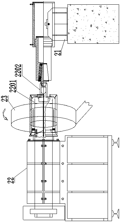

Image

  • Pneumatic telescopic center device
  • Pneumatic telescopic center device
  • Pneumatic telescopic center device

Examples


Embodiment

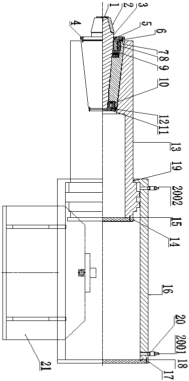
[0035] Such as figure 1 and figure 2 As shown together, the present invention provides a pneumatic retractable tip device, which includes a pneumatic unit and a tip unit, and the pneumatic unit is used to realize the telescopic function of the tip unit.

[0036] Such as figure 2 As shown, the pneumatic unit includes a cylinder assembly and a fixed seat 21; the cylinder assembly is installed on the fixed seat 21; the cylinder assembly includes a cylinder body 13, a cylinder liner 16, and a second compression sealing assembly.

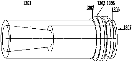
[0037] Such as image 3 As shown, the inside of the cylinder 13 is provided with a cylinder Morse taper 1301 and a cylindrical cavity; the small end surface of the cylinder Morse taper 1301 communicates with the cylindrical cavity, and the cylinder Morse taper The large end face of the taper hole of the hole 1301 coincides with one end face of the cylinder body 13; the Morse taper hole 1301 of the cylinder body is used to insert the top unit; the su...


PUM


Abstract

The invention discloses a pneumatic telescopic center device. The pneumatic telescopic center device comprises a pneumatic unit, wherein the pneumatic unit is used for realizing the telescopic function of the center unit; the pneumatic unit comprises a cylinder body, a cylinder body morse taper hole and a cylindrical cavity are formed in the cylinder body; the cylinder body morse taper hole is incommunication with the cylindrical cavity; and the cylinder body morse taper hole is used for being inserted into the center unit. According to the pneumatic telescopic center device, the pneumatic telescopic function is realized, the PLC controls the position and separation of the center device and the jacked winding drum, so that the mechanical degree is improved; the shutdown time of a tape rolling machine can be shortened several seconds, and the waste loss is reduced.

Description

technical field [0001] The invention relates to the technical field of a winding machine top, in particular to a pneumatic telescopic top device. Background technique [0002] Amorphous alloy is a new high-tech industry. With the existing production technology, it is far from reaching the advanced technology level of foreign companies. It is the current industry in the industry to realize the automation and intelligence of amorphous thin strip production equipment, increase production capacity, and reduce production costs. common issues faced. [0003] Taking the top device of the existing amorphous thin strip winding machine as an example, at present, the top device is still manually operated by various production enterprises, so that the top shaft can be in place and separated from the top reel, and the operator needs to master certain skills. Operation skills; the degree of mechanization is relatively low, and it takes a long time to adjust the position of the top, which...

Claims


Application Information

Patent Timeline
Patent Type & Authority Applications(China)
IPC IPC(8): B65H18/02
CPCB65H18/028
Inventor 滕晓群朱建华
Owner 山东海瑞得新材料科技有限公司
Learn More