Split mounting type anchor frame beam structure and construction method thereof

A frame beam and assembled technology, which is applied in basic structural engineering, excavation, construction, etc., can solve the problems of low work efficiency, insufficient strength of rock and soil, and insufficient thickness of the protective layer of the bottom reinforcement, so as to improve quality and durability. The effect of improving the overall support effect and enhancing the self-stabilizing ability of the slope

Pending Publication Date: 2019-02-19
CHINA RAILWAY ERYUAN ENG GRP CO LTD
View PDF4 Cites 11 Cited by
  • Summary
  • Abstract
  • Description
  • Claims
  • Application Information

AI Technical Summary

Problems solved by technology

[0004] 1. On-site binding of steel bars and on-site casting of concrete requires a lot of manual work, low work efficiency and high cost
[0005] 2. On-site pouring of concrete, the position of the steel bars is not easy to fix. Often, the concrete on the upper part of the frame beam has insufficient reinforcement, low strength and easy to crack, ...

Method used


Image

  • Split mounting type anchor frame beam structure and construction method thereof
  • Split mounting type anchor frame beam structure and construction method thereof
  • Split mounting type anchor frame beam structure and construction method thereof

Examples


Embodiment Construction

[0039] The present invention will be further described below in conjunction with the accompanying drawings and embodiments.

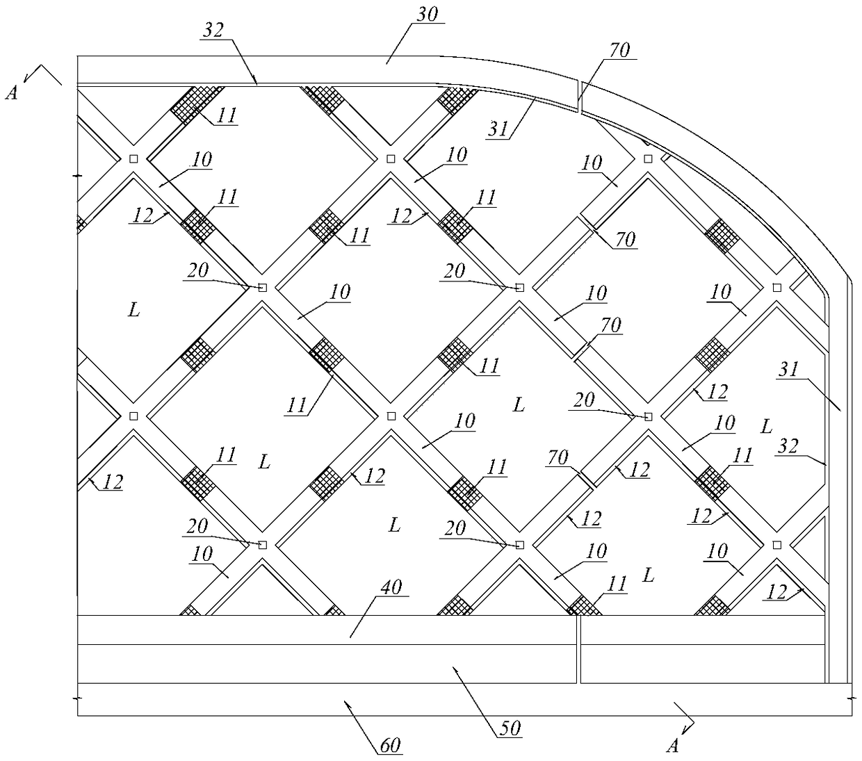
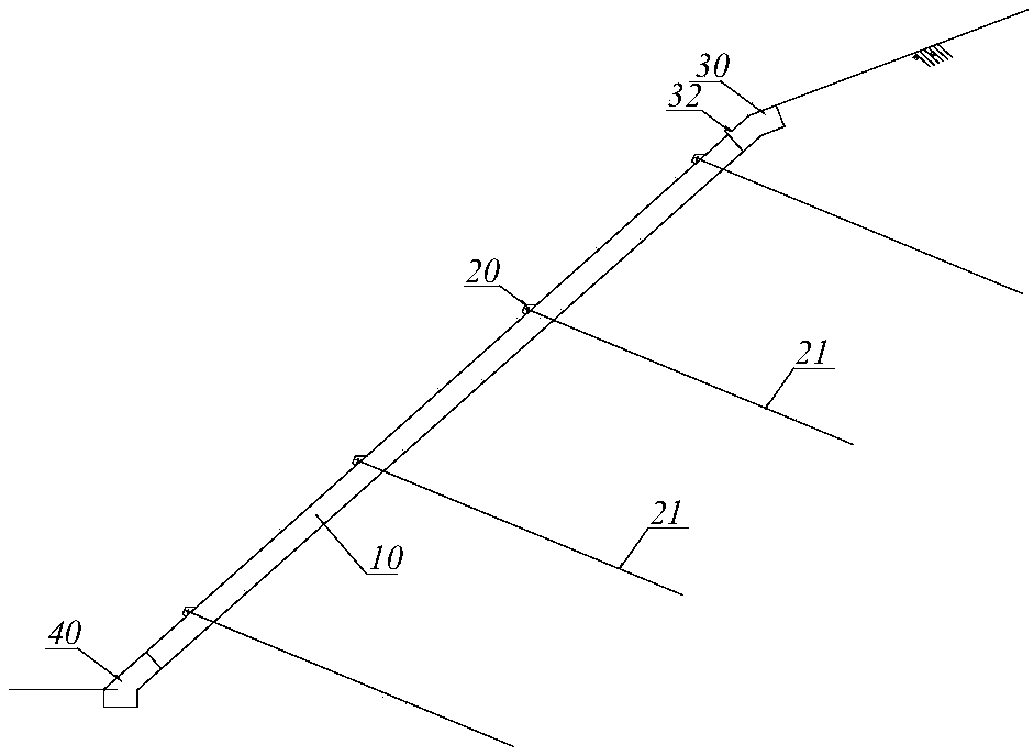
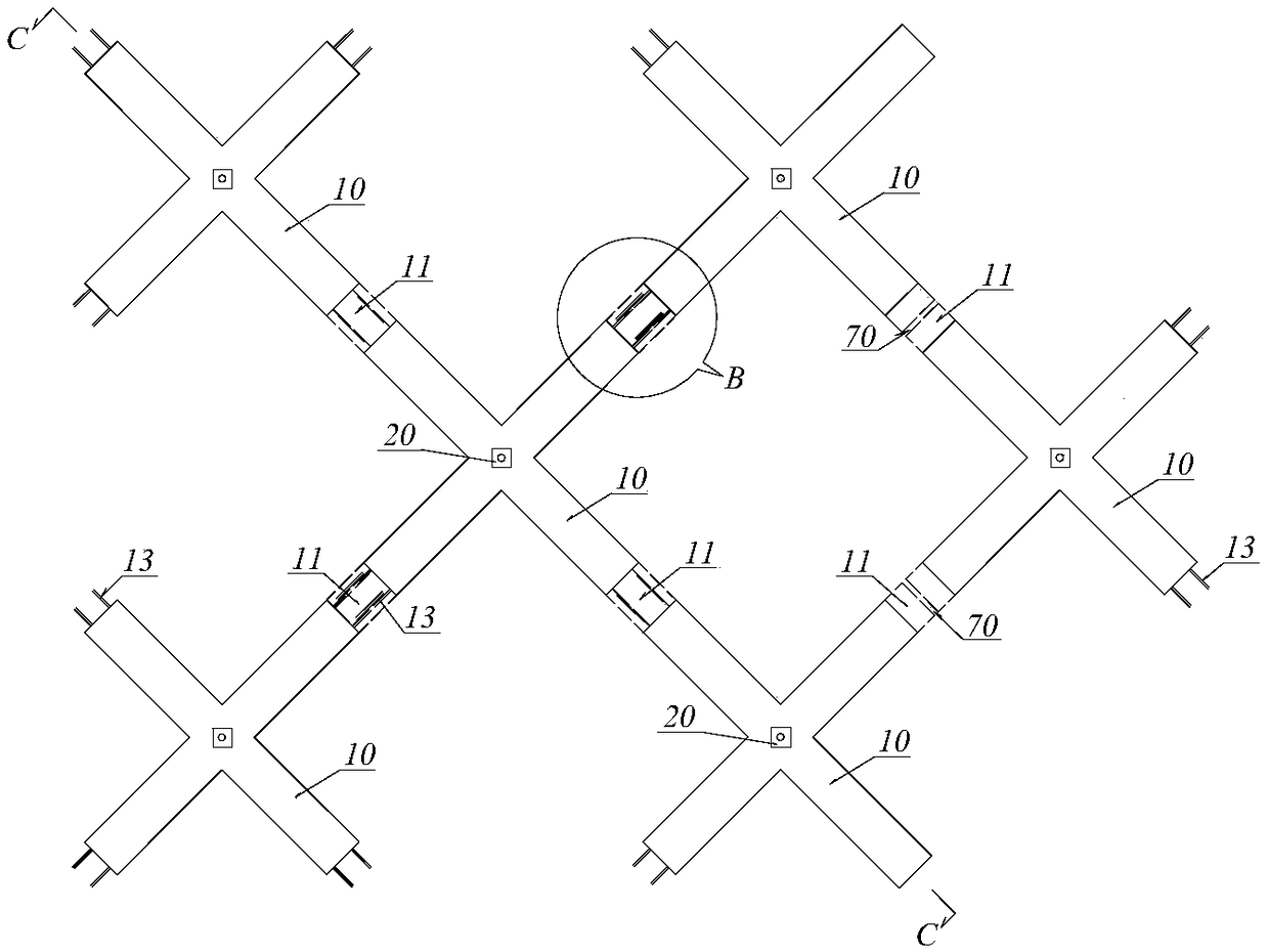
[0040] refer to figure 1 , figure 2 and image 3 , the anchor rod in an assembled anchor rod frame beam structure of the present invention includes a reinforced concrete frame beam buried under the slope surface L, and an anchor rod arranged at a node of the reinforced concrete frame beam, the inner end of the anchor rod The outer end and the outer end are respectively anchored and connected with the rock-soil layer in the slope and the reinforced concrete frame beam. The reinforced concrete frame beam is assembled by a frame beam prefabricated unit 10 with two cross limbs and a cast-in-place concrete section 11, and the corresponding limbs are butted by the cast-in-place concrete section 11 between the end faces, or by two broken The open cast-in-place concrete sections 11 form expansion joints 70 . The anchor rod is composed of a steel anchor rod...


PUM


Abstract

The invention relates to a split mounting type anchor frame beam structure and a construction method thereof. By means of the split mounting type anchor frame beam structure and the construction method, the construction efficiency and the construction quality of an anchor frame beam are effectively improved, and the overall supporting effect of the anchor frame beam structure is improved. The split mounting type anchor frame beam structure comprises reinforced concrete frame beams embedded under the slope surface of a side slope and anchor rods arranged at joints of the reinforced concrete frame beams, the inner ends and the outer ends of rod bodies of the anchor rods are correspondingly connected with a rock layer in a slope body and the reinforced concrete frame beams in an anchored manner. Each reinforced concrete frame beam is formed by split mounting of a frame beam prefabricated unit provided with two cross-shaped limbs and cast-in-place concrete sections, the corresponding limbsare in butt joint through the cast-in-place concrete sections between the end faces, or an expansion joint is formed through two disconnected cast-in-place concrete sections; and each anchor rod is composed of a steel anchor rod, a nut, a washer and a steel backing plate, wherein the nut, the washer and the steel backing plate are arranged at the exposed end of the steel anchor rod, and low prestress is applied to the steel anchor rod by screwing the nut.

Description

technical field [0001] The invention relates to the fields of retaining reinforcement for railways, highways, municipal engineering, and geotechnical engineering, in particular to an assembled bolt frame beam structure and a construction method thereof. Background technique [0002] The anchor frame beam support system has light structure, high rigidity, good reinforcement effect and greening. It is widely used in slope protection projects in the fields of railways, highways, municipalities, water conservancy and hydropower, and airports. Anchor frame beams use anchor rods to embed rock and soil, fix the frame, use frame beams to restrain slope rock and soil, prevent its displacement, improve the shallow stress of the slope, and effectively improve the overall stability of the slope. [0003] At present, anchors are often made of threaded steel, and frame beams are mainly cast-in-place reinforced concrete structures. After the slope is formed, the anchors are first installed...

Claims


Application Information

Patent Timeline
IPC IPC(8): E02D17/20E02D5/76
CPCE02D5/76E02D17/207
Inventor 薛元刘菀茹曾锐肖朝乾封志军周文洋张东卿李建国郭巍冯子亮谯春丽姜瑞雪黄鹏举彭蛟李志
Owner CHINA RAILWAY ERYUAN ENG GRP CO LTD
Why Eureka
Try Eureka