Sound absorbing device

A sound-absorbing device and sound-absorbing technology, which is applied in the field of noise reduction, can solve problems such as poor sound-absorbing performance of porous sound-absorbing materials, inability to effectively control sound waves, and a large range of influence, so as to improve sound-absorbing performance, increase sound-absorbing, Good sound absorption performance

Pending Publication Date: 2019-02-19
ZHUZHOU NAT INNOVATION RAILWAY TECH CO LTD
View PDF0 Cites 9 Cited by
  • Summary
  • Abstract
  • Description
  • Claims
  • Application Information

AI Technical Summary

Problems solved by technology

The viscous effect of the porous sound-absorbing material has a large damping effect on the high-frequency sound wave, and the sound-absorbing performance of the porous sound-absorbing material is good for the high-frequency sound wave; there is basically no viscous effect on the low-frequency sound wave, and the sound absorption of the porous sound-absorbing material Performance is poor at low frequencies
[0004] By increasing the thickness of the porous sound-absorbing material, the viscous effect on low-frequency sound waves can be increased, thereby increasing the sound-absorbing performance of low-frequency sound waves; however, porous sound-absorbing materials have a "bottleneck" of low-frequency sound absorption under the limited size and weight constraints , that is: the sound waves with large wavelengths in the low frequency range cannot be effectively controlled, and the low frequency sound waves are not easy to attenuate in the air, the propagation distance is long, and the influence range is large. To effectively reduce low frequency noise, the thickness of the porous sound-absorbing material must be greatly increased

Method used


Image

  • Sound absorbing device
  • Sound absorbing device
  • Sound absorbing device

Examples


Embodiment approach

[0047] refer to figure 1 , As an embodiment of the present invention, the porous sound-absorbing device 1 of the present invention includes one or more than two porous sound-absorbing layers; the porous sound-absorbing layers can be connected by bonding. The porous sound-absorbing layer of the present invention is a porous sound-absorbing material, which can be glass fiber cotton, melamine foam, polyurethane fiber or polyurethane foam; but is not limited to the above types, and can be any porous sound-absorbing material. The sound absorption of more than two porous sound-absorbing layers is closely related to the numerous fine pores inside the porous sound-absorbing layer. The pores are connected to each other and extend to the outer surface to connect with the outside world. Two parts, one of which is reflected and reflected into the adjacent porous sound-absorbing layer, and the remaining part is transmitted to the inside of the porous sound-absorbing layer, and the sound wa...

Embodiment 1

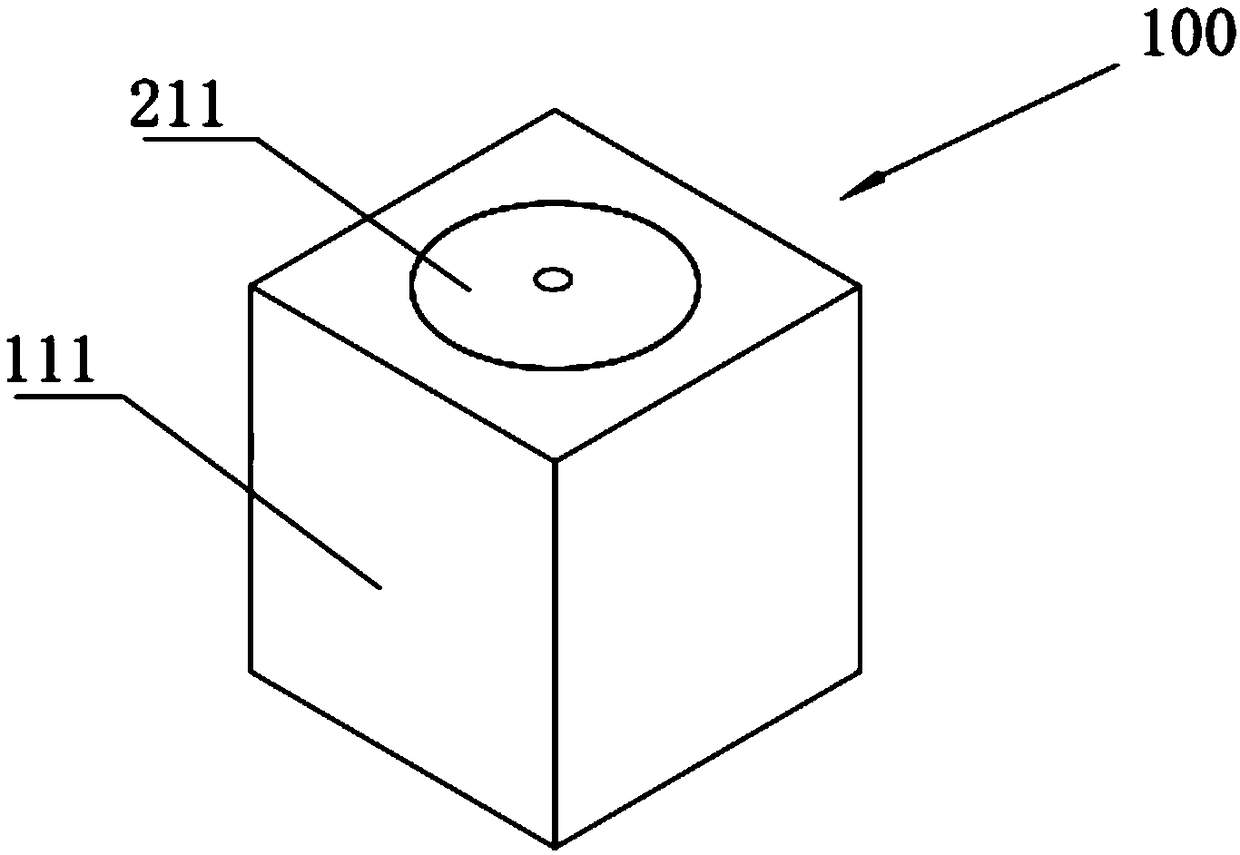
[0077] see figure 1 , the sound-absorbing unit body 100 includes a porous sound-absorbing device 1 and a resonant sound-absorbing device 2,

[0078] The porous sound-absorbing device 1 includes a first porous sound-absorbing layer 111, the material of the first porous sound-absorbing layer 111 is glass fiber cotton; the length and width of the first porous sound-absorbing layer 111 are 120mm, The thickness of the first porous sound-absorbing layer 111 is 70mm, and the density is 10Kg / m 3 , the flow resistance rate is 3175N·s / m 4 .

[0079] The first porous sound-absorbing layer 111 is provided with a lumen 14, and the corresponding lumen 14 is a first resonant tube 211; the first resonant tube 211 is embedded in the first porous sound-absorbing layer 111;

[0080] The first resonance tube 211 is a cylindrical tube with a diameter of 40 mm, a height of 70 mm, and a thickness of 1 mm;

[0081] The top of the first resonant tube 211 is provided with a through hole, and the so...

Embodiment 2

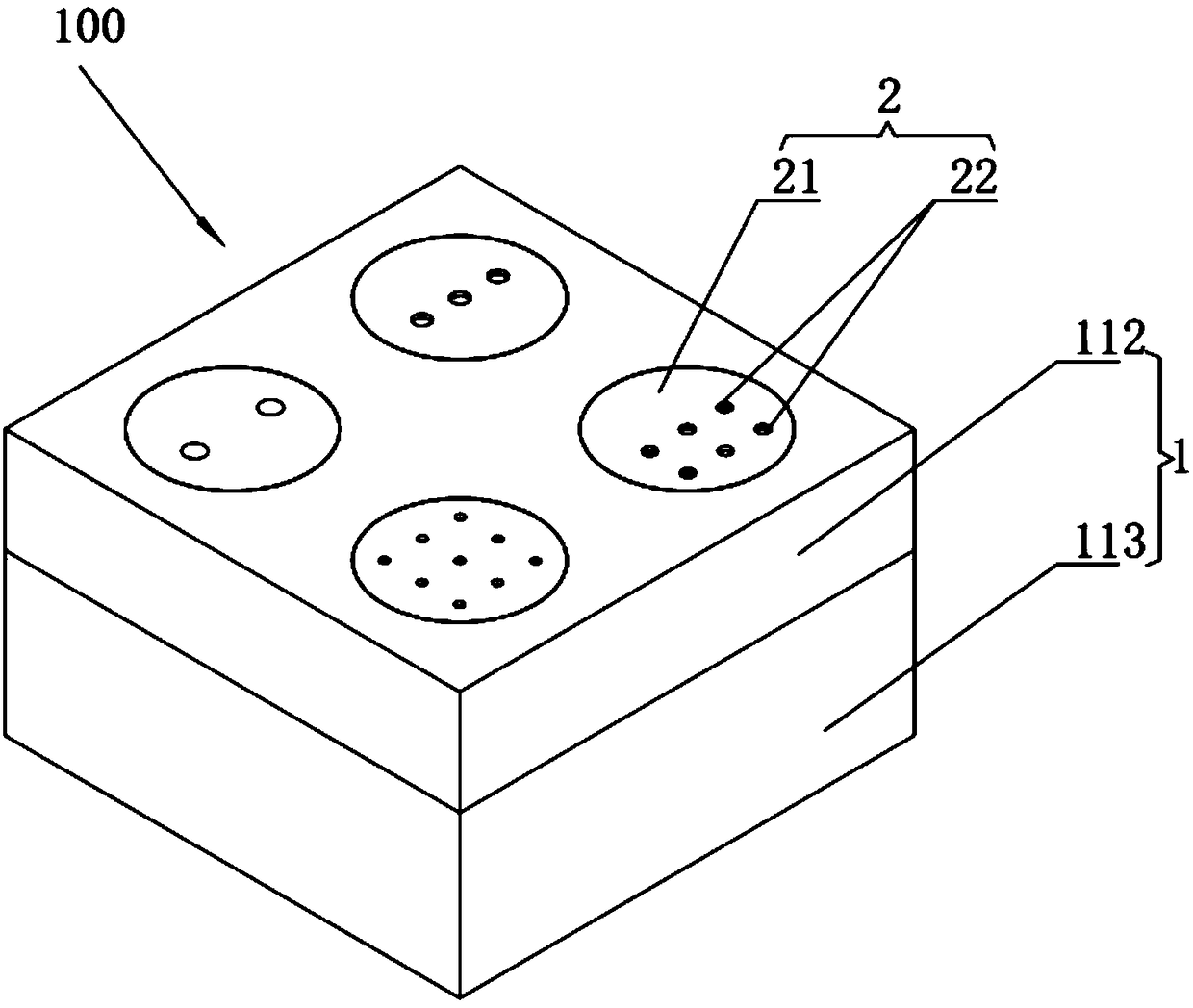
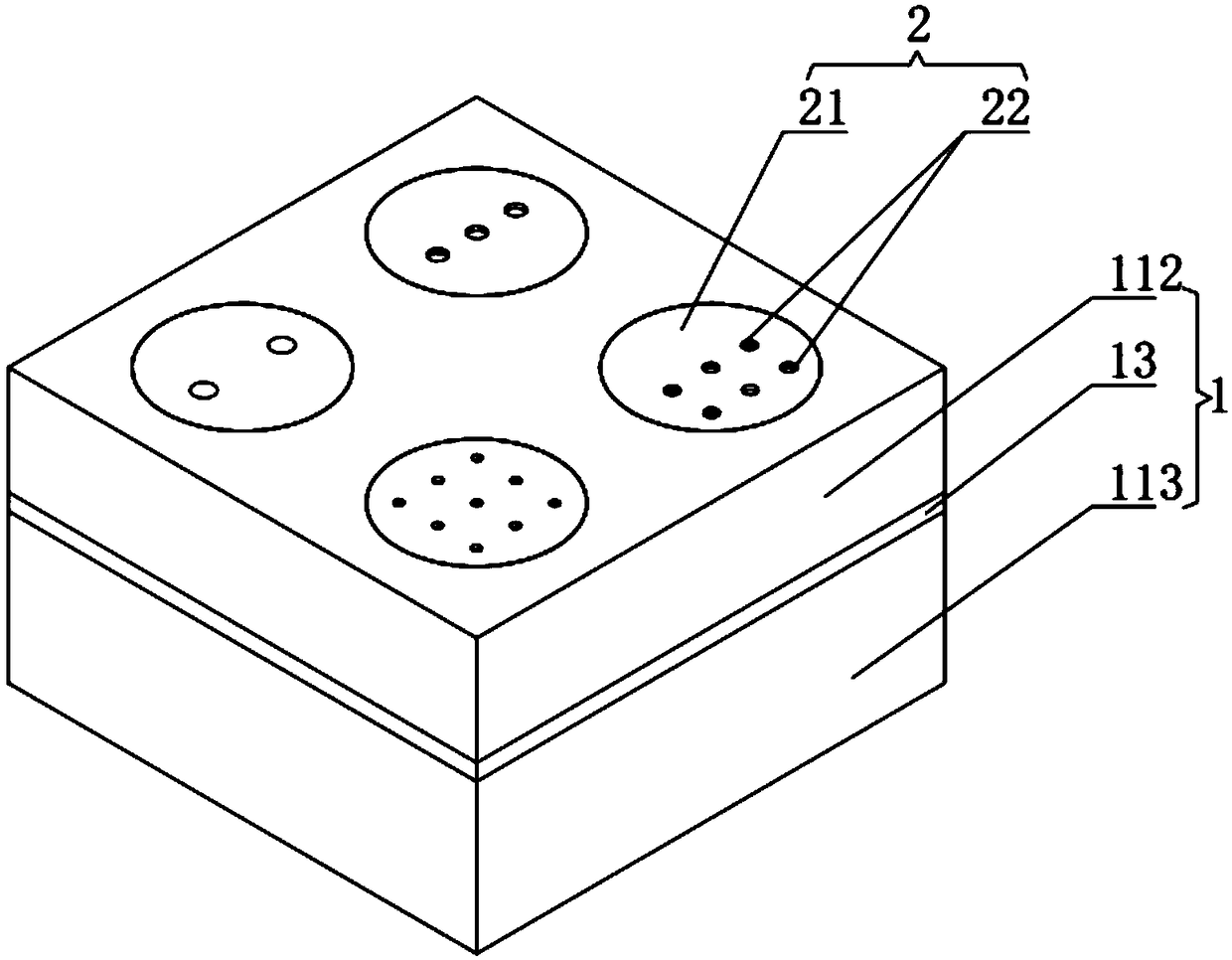
[0083] see figure 2 , Figure 10 and Figure 11 , different from Embodiment 1, the sound-absorbing unit body 100 includes a porous sound-absorbing device 1 and a resonant sound-absorbing device 2, and the porous sound-absorbing device 1 includes a second porous sound-absorbing layer 112 and a third porous sound-absorbing layer 112 sound-absorbing layer 113 . The second porous sound-absorbing layer 112 and the third porous sound-absorbing layer 113 are bonded by glue.

[0084] The material of the second porous sound-absorbing layer 112 is melamine foam; the length and width of the second porous sound-absorbing layer 112 are 120mm, the thickness of the second porous sound-absorbing layer 2 is 20mm, and the density is 10Kg / m 3 , the flow resistance rate is 4200N·s / m 4.

[0085] The material of the third porous sound-absorbing layer 113 is polyurethane fiber; the length and width of the third porous sound-absorbing layer 113 are 120mm, the thickness of the third porous sound...


PUM


Abstract

The invention belongs to the technical field of noise reduction, and discloses a sound absorbing device. The sound absorbing device comprises a sound absorbing unit body, and the sound absorbing unitbody comprises a porous sound absorbing device and a resonant sound absorbing device; the porous sound absorbing device comprises a porous sound absorbing layer, and a tube cavity is formed in the porous sound absorbing layer; the resonant sound absorbing device comprises a resonant tube and a sound absorbing tube; the resonant tube is mounted in the tube cavity in a matched mode; and a through hole is formed in the top of the resonant tube, the sound absorbing tube is mounted in the through hole in a matched mode, and both the two ends, in the resonant tube, of the sound absorbing tube are open. The sound absorbing device is provided with the porous sound absorbing device and the resonant sound absorbing device, thus a parallel sound absorbing structure is formed, and the overall sound absorbing performance to low, medium and high frequency wide band sound waves is good; and the sound absorbing performance can be improved within the limited thickness.

Description

technical field [0001] The invention belongs to the technical field of noise reduction, and in particular relates to a sound absorbing device. Background technique [0002] In the construction of modern urbanization, along with the rapid development of industry, construction and transportation, the population density is expanding rapidly. Noise pollution has become one of the pollutions faced by human beings, just like air pollution. Noise pollution has unique characteristics. The harm is mainly in the following three aspects: (1) affect sleep, which can cause nervous system diseases; (2) damage the auditory organs; (3) affect physical health, may accelerate the aging of the heart, cause nervous system disorders, and inability to concentrate, etc. symptom. [0003] The application of sound-absorbing materials to realize noise control is an important way of noise prevention and control. At present, the commonly used sound-absorbing materials are porous sound-absorbing mater...

Claims


Application Information

Patent Timeline
Patent Type & Authority Applications(China)
IPC IPC(8): E04B1/84G10K11/162G10K11/168G10K11/172
CPCE04B1/8404E04B2001/8433E04B2001/848G10K11/162G10K11/168G10K11/172
Inventor 李登科李林
Owner ZHUZHOU NAT INNOVATION RAILWAY TECH CO LTD
Why Eureka
Try Eureka