
Simple cycle engine with combustion chamber driven compressor by continuously variable transmission

A continuously variable transmission and simple cycle technology, which is applied in the direction of machines/engines, gas turbine devices, mechanical equipment, etc., can solve the problems of low miniaturization efficiency, insufficient efficiency, and many parts

Active Publication Date: 2020-12-18
钱裕智
View PDF6 Cites 0 Cited by
  • Summary
  • Abstract
  • Description
  • Claims
  • Application Information

AI Technical Summary

Problems solved by technology

[0002] The structure of the existing piston engine is complicated, and the efficiency is not high enough; the efficiency of the best gasoline engine is generally around 30% during normal operation, and Mazda’s second-generation Skyline engine will reach 50% by 2019. Due to emission restrictions, the piston engine has never been The efficiency of reaching the limit will not be greatly improved; the efficiency of diesel engines is better, but the comfort is poor and heavy; the efficiency of steam turbines is low; the efficiency of gas turbines is low at low speeds, and the efficiency of miniaturization is low. too much

Method used


Image

  • Simple cycle engine with combustion chamber driven compressor by continuously variable transmission
  • Simple cycle engine with combustion chamber driven compressor by continuously variable transmission
  • Simple cycle engine with combustion chamber driven compressor by continuously variable transmission

Examples


Embodiment Construction

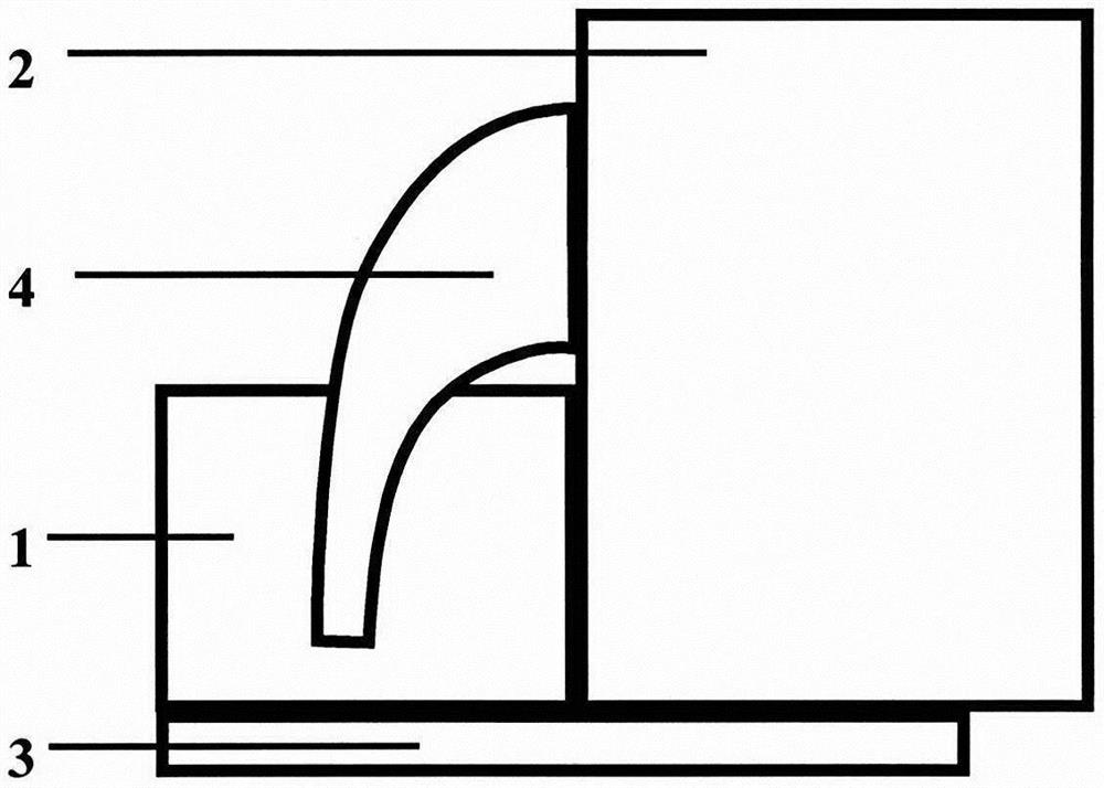
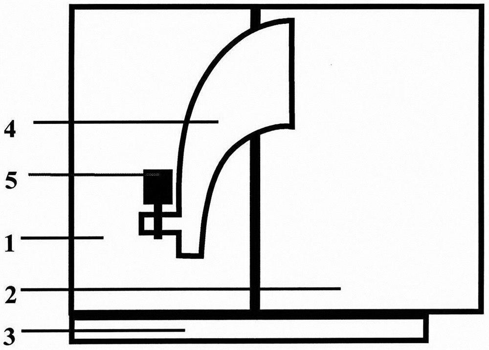
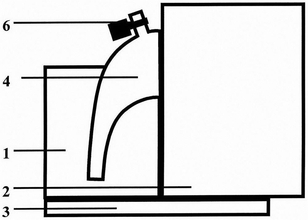
[0038] figure 1 , 2 , 3, the compressor (1) and the wind-driven motor (2) in the basic work system can adopt various compressors and wind-driven motors that can continuously produce or consume compressed air or consume gas, such as star piston compressors, Sliding vane compressors, scroll compressors, centrifugal compressors, axial flow compressors, mixed flow compressors, etc., various volume and speed compressors, and the wind engine corresponds to star piston air Engine, sliding vane rotor wind engine, vortex wind engine, centrifugal wind engine, axial flow wind engine, mixed flow wind engine, etc. various volume and speed wind engines; The type of compressor (1) and the type of wind-driven engine (2) are matched according to different situations. For example, small and medium-sized engines can choose volumetric scroll compressors, sliding vane compressors, etc. Engines, sliding vane rotor wind engines, etc. are self-matched or mixed and matched. In addition to the volum...


PUM


Abstract

The invention provides a simple cycle engine with a combustion chamber and a compressor driven by a steeples speed change device. The simple cycle engine with the combustion chamber and the compressordriven by the steeples speed change device is the simple cycle engine, and can also be a combined cycle engine. A basic working system of the simple cycle engine mainly comprises the compressor, a fuel gas compressed air engine, an independent combustion chamber connected to the compressor and the fuel gas compressed air engine, and the steeples speed change device. When the basic working systemworks, the compressor continuously produces compressed air and conveys the compressed air to the combustion chamber, the compressed air and fed fuel are mixed and combusted, and gas absorbs heat and expands at a constant pressure to push the fuel gas compressed air engine to rotate, so that the fuel gas compressed air engine does the constant pressure expansion work; then fuel gas generated aftercombustion enters the fuel gas compressed air engine, so that the fuel gas compressed air engine does the adiabatic expansion work; and the steeples speed change device is arranged on the compressor and a power transmission shaft of the fuel gas compressed air engine, is used for adjusting the speed ratio of the compressor to the compressed air engine and changing the volume ratio of the compressor to the compressed air engine in a disguised form and the expansion ratio, ensures the stable pressure intensity of the combustion chamber when the air, fuel, and load speed of the combustion chamberchange, and causes the pressure intensity of an air outlet of the fuel gas compressed air engines to be lightly higher than the atmospheric pressure.

Description

technical field [0001] The invention relates to a heat engine, which is a high-efficiency simple cycle engine with an independent combustion chamber and a compressor driven by a stepless transmission, and a gas-steam combined cycle engine when there is a waste heat utilization system. Background technique [0002] The structure of the existing piston engine is complicated, and the efficiency is not high enough; the efficiency of the best gasoline engine is generally around 30% during normal operation, and Mazda’s second-generation Skyline engine will reach 50% by 2019. Due to emission restrictions, the piston engine has never been The efficiency of reaching the limit will not be greatly improved; the efficiency of diesel engines is better, but the comfort is poor and heavy; the efficiency of steam turbines is low; the efficiency of gas turbines is low at low speeds, and the efficiency of miniaturization is low. too much. Contents of the invention [0003] The object of th...

Claims


Application Information

Patent Timeline
Patent Type & Authority Patents(China)
IPC IPC(8): F02C3/04F02C6/20F01K23/10F01K27/00
CPCF01K23/10F01K27/00F02C3/04F02C6/20
Inventor 钱裕智钱百成
Owner 钱裕智
Learn More