
Terrain inversion method of radar altimeter under undulating terrain

An altimeter and terrain technology, applied in the fields of radar data processing and wireless communication, can solve the problems of low measurement accuracy, unsuitable for high-precision altimetry of low-altitude aircraft, and inability to use undulating terrain features to invert, and achieve high measurement accuracy. Effect

Active Publication Date: 2019-02-19
XIDIAN UNIV
View PDF12 Cites 11 Cited by
  • Summary
  • Abstract
  • Description
  • Claims
  • Application Information

AI Technical Summary

Problems solved by technology

However, the disadvantage of this method is that the frequency corresponding to the maximum peak crossing the threshold is the echo beat frequency of the scattering point directly below the radar. For the echo beat frequency of the scattering point below, the frequency corresponding to the maximum peak value passing the threshold is the echo beat frequency of the scattering point directly below the radar, which will cause ambiguity in the radar height inversion and cannot be used for undulating terrain feature reflection. play
However, the disadvantage of this method is that it is necessary to pre-store the ground digital topographic map of the flight area where the aircraft is located in advance, and the measurement accuracy of the aircraft position is related to the accuracy of the digital topographic map. When the coverage accuracy of the digital topographic map is low, the measurement accuracy Low, not suitable for high-precision altimetry of low-altitude aircraft

Method used

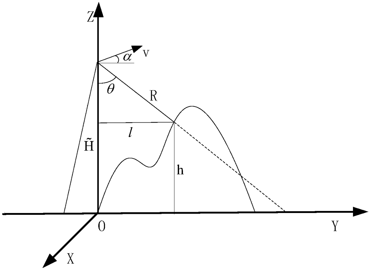
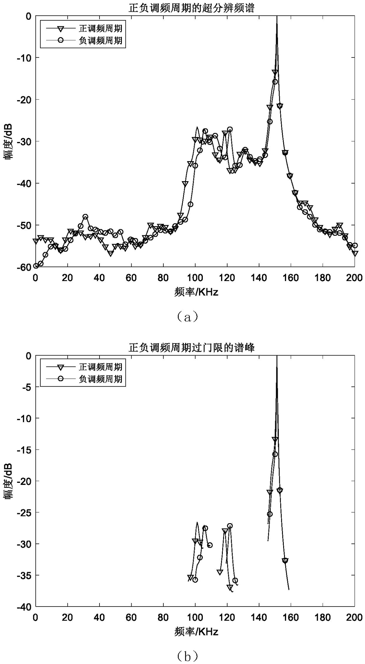

Image

  • Terrain inversion method of radar altimeter under undulating terrain
  • Terrain inversion method of radar altimeter under undulating terrain
  • Terrain inversion method of radar altimeter under undulating terrain

Examples


Embodiment Construction

[0049] The present invention will be further described below in conjunction with the accompanying drawings.

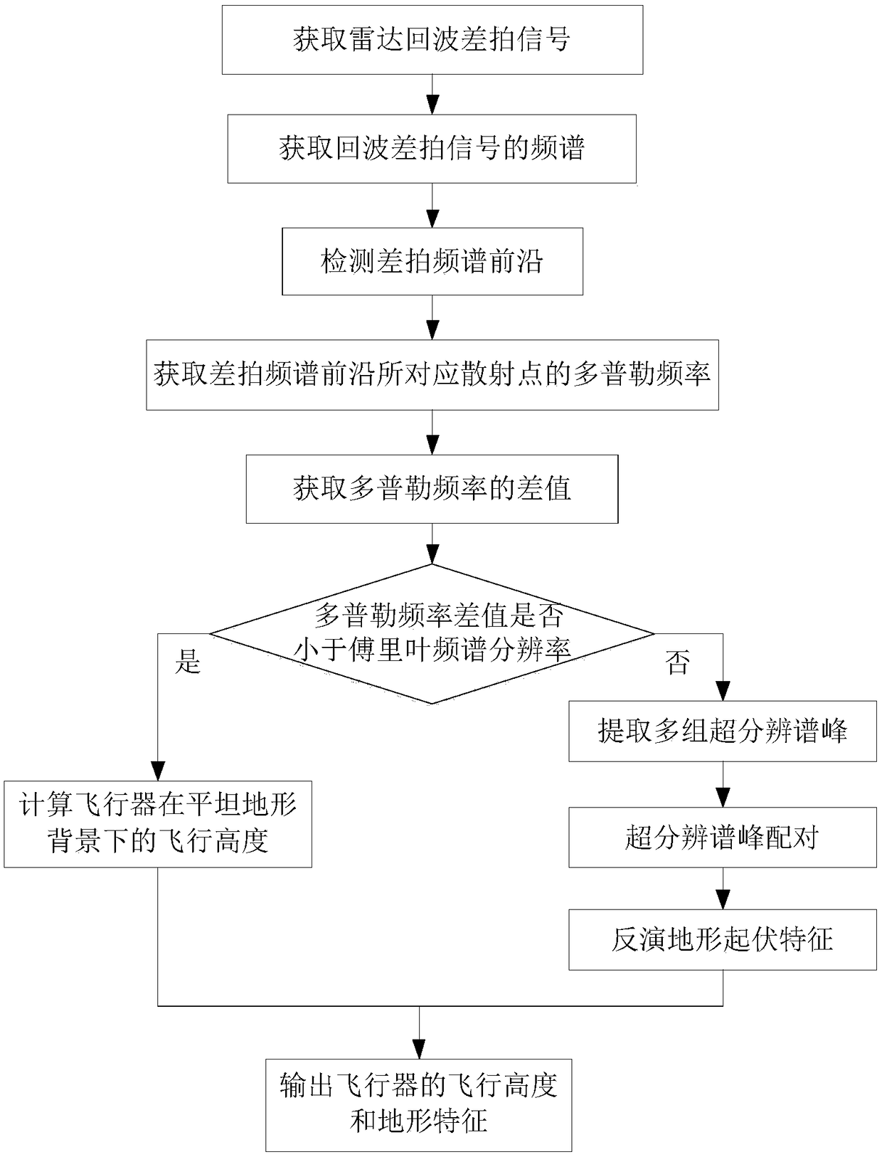
[0050] refer to figure 1 , to further describe the specific implementation steps of the present invention.

[0051] Step 1: Obtain the beat signal of the radar echo.

[0052] From the receiver of the altimeter radar on the aircraft, read the echo beat signal sampled by the receiver in a positive and negative frequency modulation cycle of the altimeter radar transmission signal.

[0053] Step 2, acquiring the frequency spectrum of the echo beat signal.

[0054] Copy a group of echo beat signal data, process two sets of data in parallel, perform fast Fourier transform on the original data, obtain the Fourier spectrum of the echo beat signal data, and perform Capon super-resolution spectrum on the copied data to obtain Super-resolved spectrum of echo beat signal data.

[0055] When performing Capon super-resolution spectrum on the echo data sequence, there is only one...


PUM


Abstract

The invention provides a terrain inversion method of a radar altimeter under an undulating terrain. The terrain inversion method comprises the following steps of: obtaining radar echo beat signals; obtaining a spectrum of the echo beat signals; detecting the leading edge of a beat spectrum; obtaining the Doppler frequency of scattering points corresponding to the leading edge of the beat spectrum;obtaining a Doppler frequency difference; determining whether the Doppler frequency difference is less than the Fourier spectrum resolution; if so, calculating the flight altitude of an aircraft in aflat terrain, and outputting a flight altitude and topographical features of the aircraft; otherwise, extracting multiple sets of super-resolution peaks; pairing super-resolution peaks; retrieving topographic relief features; and outputting the flight altitude and the terrain characteristics of the aircraft. According to the terrain inversion method of the radar altimeter under the undulating terrain, the distances of multiple scattering points and the Doppler frequency are obtained by extracting multiple sets of super-resolution peaks and performing spectrum pairing with the least variance spectral pairing method to invert the terrain relief characteristics. The terrain inversion method can be used for accurate altimetry of low altitude aircraft and terrain undulating characteristics inversion under the undulating terrain.

Description

technical field [0001] The invention belongs to the technical field of wireless communication, and further relates to a terrain inversion method of a radar altimeter under a background of undulating terrain in the technical field of radar data processing. The invention can be applied to reverse the fluctuation characteristics of the earth's surface terrain by using the echo data of the radar altimeter. Background technique [0002] A radar altimeter is a device mounted on an aircraft that uses the time delay of electromagnetic wave propagation to measure the height from the flight platform to the ground. Terrain inversion is the use of altimeter data from radar altimeters to reverse the undulation characteristics of terrain. At present, there are two main types of commonly used methods for terrain inversion using radar altimetry data, namely analytical methods and statistical methods. The analytical method is mainly based on the response function, using the surface gravity...

Claims


Application Information

Patent Timeline
IPC IPC(8): G01S13/88G01S7/41
CPCG01S7/41G01S13/882
Inventor 杨志伟李相海雷赫黄帅张攀
Owner XIDIAN UNIV
Learn More