Gate triggering control method for thyristor

A technology of gating control and trigger control, which is applied in the direction of control/regulation system, regulation of electrical variables, instruments, etc., can solve problems such as power supply short circuit fault, poor real-time performance, and controller time delay, and achieve the effect of strengthening protection

Inactive Publication Date: 2019-02-19
HUNAN UNIV OF TECH
View PDF3 Cites 0 Cited by
  • Summary
  • Abstract
  • Description
  • Claims
  • Application Information

AI Technical Summary

Problems solved by technology

[0003] At present, controllers such as single-chip microcomputers and PLCs are mainly used to judge the level of input voltage and divide the voltage range, and software logic is used to realize the switching and interlocking of the combination control of multiple thyristor electronic switches. The advantage is flexible control, but the controller processing is uniform. There is a time delay, the real-time performance is poor, and problems such as running programs and crashes in single-chip microcomputers and PLCs will also cause the voltage regulator to fail to work, or cause short-circuit faults in the power supply due to software control logic errors.

Method used


Image

  • Gate triggering control method for thyristor
  • Gate triggering control method for thyristor
  • Gate triggering control method for thyristor

Examples


Embodiment Construction

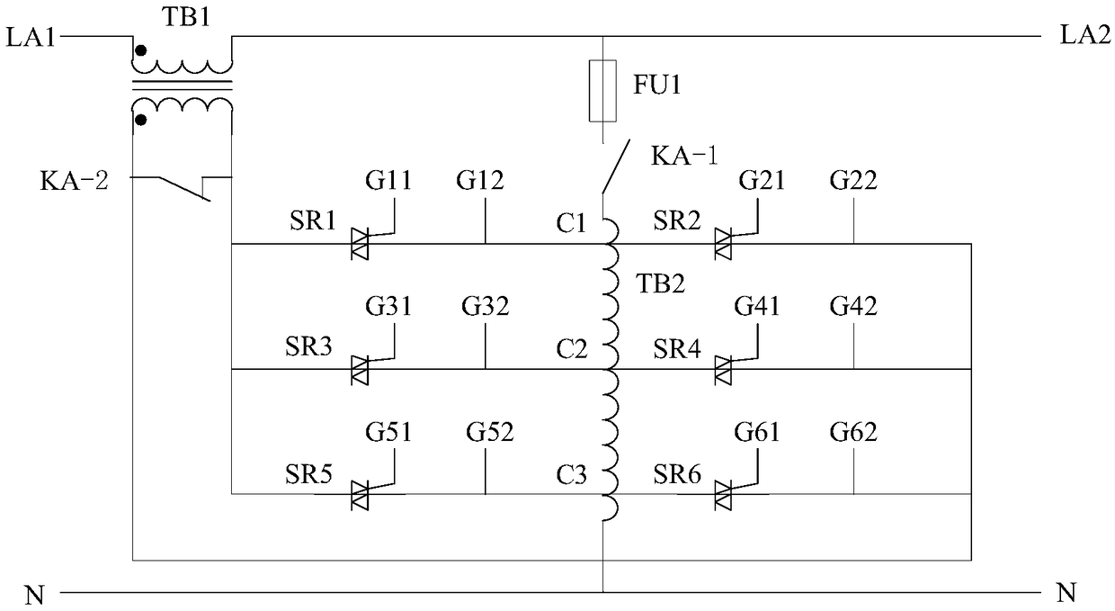
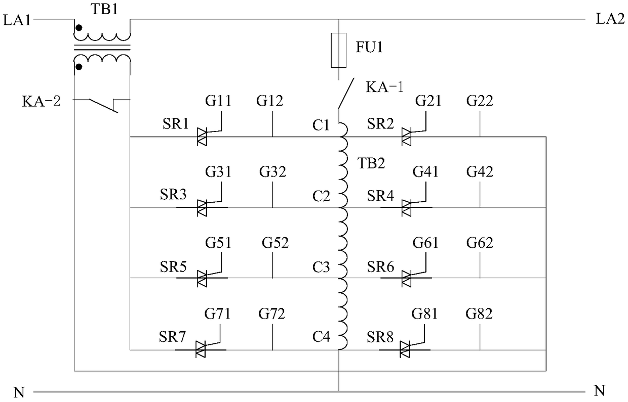
[0040] In the following, the present invention will be further described through the application of the thyristor trigger gating control method and the circuit in the partition auto-compensation AC voltage stabilizer in conjunction with the accompanying drawings.

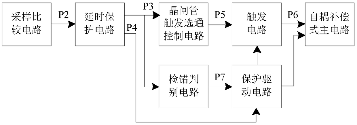
[0041] figure 1 It is a block diagram of the partitioned self-coupling compensation AC voltage regulator, the sampling comparison circuit samples the AC power supply voltage, and outputs the trigger gating control value P2; the delay protection circuit inputs the trigger gating control value P2, and outputs the delayed trigger gating control value The control value P3 and the non-trigger area control signal P4; the thyristor trigger gating control circuit inputs the delayed trigger gating control value P3, and outputs the trigger control signal P5; the trigger circuit sends the trigger signal P6 to the self according to the input trigger control signal P5 The main circuit of the coupling compensation type controls t...


PUM


Abstract

The invention provides a gate triggering control method for a thyristor. The method is used for a combined controlling of the on-off of the thyristor in a thyristor switching group. According to a gate triggering control value, the combined state of the on-off of thyristors in the thyristor switch group is controlled by selecting and validating corresponding trigger control signals through a diodegate triggering matrix. When the gate triggering control method for the thyristor is used for a partition self-coupled compensation AC voltage regulator, a sampling comparison circuit performs a voltage sampling on an AC power supply voltage, and outputs the gate triggering control value; and a gate triggering control circuit for the thyristor outputs the trigger control signals according to thedelayed gate triggering control value, and controls the on-off of bidirectional thyristors in the thyristor switch group. While an interlocking control is realized, the open circuit protection of thehyristor switching group is started / stopped by the error detection judgment unit and the protection driving circuit according to whether the trigger gating control value is valid or not, and the powersupply of the trigger unit is controlled, so that the protection strength of abnormities during working is effectively enhanced.

Description

technical field [0001] The invention relates to the technical field of power supplies, in particular to a thyristor trigger gate control method. Background technique [0002] The existing compensated AC voltage stabilizer has the advantages of wide voltage stabilization range, almost no waveform distortion, high overall efficiency and strong load adaptability. The principle is to automatically control the switching of different winding coils of the primary winding on the compensation transformer according to the level of the input voltage, using the ratio relationship between the primary side working winding and the secondary winding, or by adjusting the voltage applied to the primary winding , providing bidirectional and multi-level voltage compensation, so as to achieve the purpose of voltage regulation and stabilization. [0003] At present, controllers such as single-chip microcomputers and PLCs are mainly used to judge the level of input voltage and partition the volta...

Claims


Application Information

Patent Timeline
Patent Type & Authority Applications(China)
IPC IPC(8): G05F1/20
CPCG05F1/20
Inventor 舒中宾凌云文定都
Owner HUNAN UNIV OF TECH
Why Eureka
Try Eureka