Perovskite solar cell structure

A solar cell and perovskite technology, applied in circuits, photovoltaic power generation, electrical components, etc., can solve the problems of poor stability and high cost of production materials for perovskite solar cells

Pending Publication Date: 2019-02-19
EZHOU INST OF IND TECH HUAZHONG UNIV OF SCI & TECH +1
View PDF3 Cites 0 Cited by
  • Summary
  • Abstract
  • Description
  • Claims
  • Application Information

AI Technical Summary

Problems solved by technology

[0005] The technical problem to be solved by the present invention is that in the technology of perovskite solar cel

Method used


Image

  • Perovskite solar cell structure
  • Perovskite solar cell structure
  • Perovskite solar cell structure

Examples


Embodiment 1

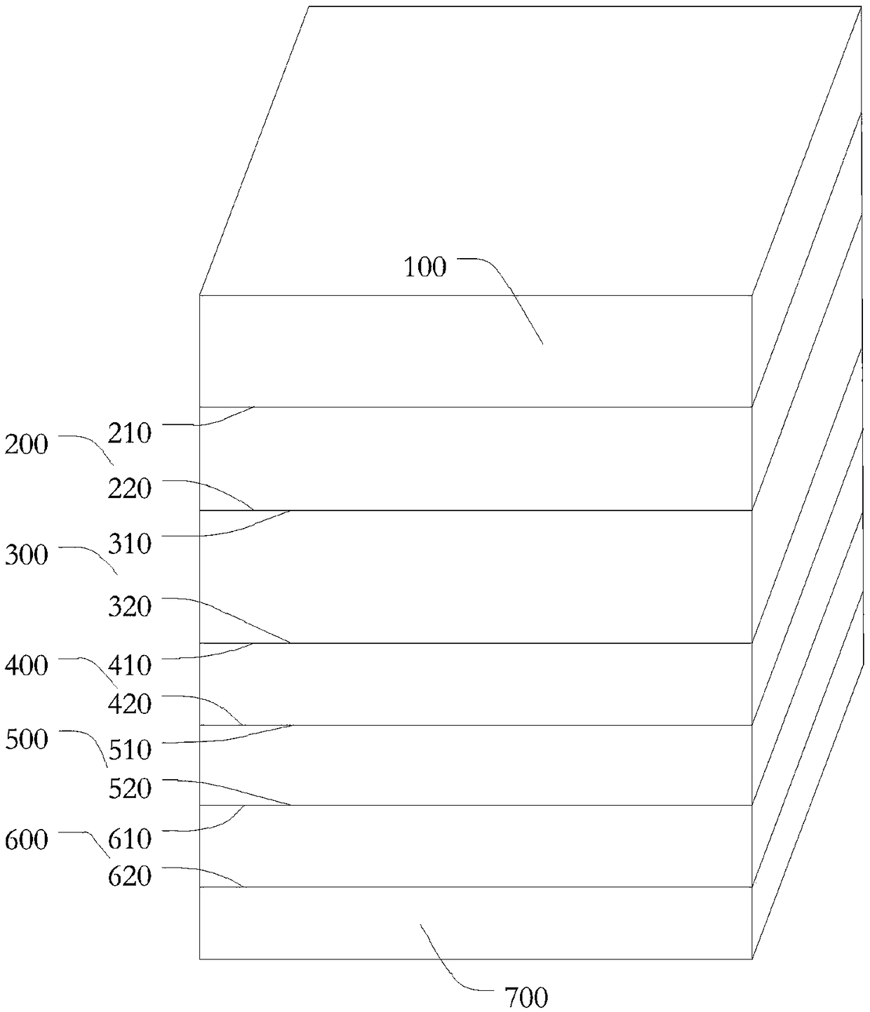
[0029] See figure 1 , figure 1 It is a schematic diagram of the overall structure of a perovskite solar cell provided by an embodiment of the present invention. The embodiment of the present invention provides a perovskite solar cell, and the perovskite solar cell includes an inert semi-metal electrode layer 100, an electron transport layer 200, the perovskite film layer 300, the hole transport layer 400, the transparent conductive electrode 500 and the glass substrate 600, the inert semi-metal electrode layer 100, the electron transport layer 200, the perovskite film layer 300, the hole transport layer Layer 400, transparent conductive electrode 500 and glass substrate 600 are described in detail below:

[0030] For the inert semi-metal electrode layer 100:

[0031] The material for making the inert half-metal electrode layer 100 may be Bi element; or, the material for making the inert half-metal electrode layer 100 may be Sb element. The thickness of the inert semi-metal ...

Embodiment 2

[0069] See Figure 9 as shown, Figure 9 It is a flowchart of a method for manufacturing a perovskite solar cell provided by an embodiment of the present invention. Embodiment 2 of the present invention provides a method for manufacturing a perovskite solar cell. The method for manufacturing a perovskite solar cell includes:

[0070] Step S100, obtaining the FTO electrode layer 700, and preparing a glass substrate 600 on the FTO electrode layer 700;

[0071] Specifically, the glass substrate 600 can be prepared on the surface of the FTO electrode layer 700 in an existing conventional manner, for example, the FTO electrode can be coated by spin coating, doctor blade coating or slit coating. Layer 700 is plated on the surface of FTO electrode layer 700 . The FTO electrode layer 700 and the glass substrate 600 can be made parallel to each other. In this way, the technical effect that the FTO electrode layer 700 and the glass substrate 600 can be fabricated sequentially from b...


PUM

PropertyMeasurementUnit
Thicknessaaaaaaaaaa
Melting pointaaaaaaaaaa
Boiling pointaaaaaaaaaa

Abstract

The invention discloses a perovskite solar cell structure, and belongs to the technical field of solar cell preparation. The perovskite solar cell structure comprises an inert semi-metal electrode layer, a hole transporting layer, a perovskite film layer, an electron transfer layer, a transparent conducting electrode and a glass substrate, the hole transporting layer is provided with a first sidesurface and a second side surface and arranged on the inert semi-metal electrode layer through the first side surface, the perovskite film layer is provided with a third side surface and a fourth sidesurface and arranged on the second side surface through the third side surface, the electron transfer layer is provided with a fifth side surface and a sixth side surface and arranged on the fourth side surface through the fifth side surface, the transparent conducting electrode is provided with a seventh side surface and an eighth side surface and arranged on the sixth side surface through the seventh side surface, and the glass substrate is provided with a ninth side surface and a tenth side surface and arranged on the eighth side surface through the ninth side surface. The structure has the advantages that the production cost of a cell is reduced, and stability is improved.

Description

technical field [0001] The invention belongs to the technical field of solar cell preparation, and in particular relates to a structure of a perovskite solar cell. Background technique [0002] With the increasing shortage of traditional fossil energy, people pay more and more attention to the research of renewable energy, especially solar cells. Traditional crystalline silicon solar cells are relatively expensive, complex in process, and have strict requirements on production equipment, while the new generation of dye-sensitized cells and organic solar cells are too inefficient and have poor stability. Perovskite solar cells have the advantages of high photoelectric conversion efficiency and extensive industrialization. [0003] At present, in the existing technologies for perovskite solar cells, perovskite solar cells are usually made of expensive metals such as Au and Ag as electrode materials. However, under the action of water vapor, perovskite solar cell devices and ...

Claims


Application Information

Patent Timeline
IPC IPC(8): H01L51/42H01L51/44H01L51/46
CPCH10K30/81H10K30/30H10K2102/00Y02E10/549Y02P70/50
Inventor 陈炜陈锐
Owner EZHOU INST OF IND TECH HUAZHONG UNIV OF SCI & TECH
Why Eureka
Try Eureka