Arc extinction device and method capable of being used for alternating-current and direct-current circuit breaker of power grid

A technology of DC circuit breakers and circuit breakers, applied in emergency protection circuit devices, circuit devices, emergency protection circuit devices for limiting overcurrent/overvoltage, etc., can solve problems such as lack of high-voltage DC circuit breakers, and reduce power grid cost, effect of eliminating overvoltage

Pending Publication Date: 2019-02-19
王雪燕 +1
View PDF12 Cites 0 Cited by
  • Summary
  • Abstract
  • Description
  • Claims
  • Application Information

AI Technical Summary

Problems solved by technology

[0017] At present, one of the main reasons restricting the practical application of flexible DC transmission (distribution) networks is the lack of practical high-voltage DC circuit breakers. The main reason is that the existing technology cannot solve the problem of arc extinguishing of DC circuits well.

Method used


Image

  • Arc extinction device and method capable of being used for alternating-current and direct-current circuit breaker of power grid
  • Arc extinction device and method capable of being used for alternating-current and direct-current circuit breaker of power grid
  • Arc extinction device and method capable of being used for alternating-current and direct-current circuit breaker of power grid

Examples


Embodiment 1

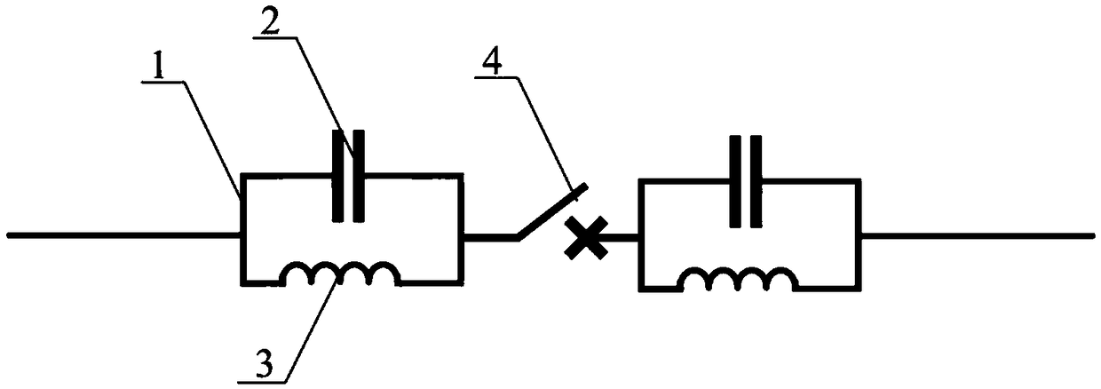
[0064] Example as figure 1 As shown, this embodiment is aimed at the wiring mode of an air circuit breaker (air switch), etc., including a parallel self-discharge circuit 1 , a capacitor gap 2 , an inductance coil 3 and a circuit breaker 4 . Wherein two parallel self-discharging circuits are connected in series on the branch of the circuit breaker, the positions connected in series of the parallel self-discharging circuits are respectively located at the front and rear of the circuit breaker, and the inductance coil is connected in parallel with the capacitance gap to form a parallel connection self-discharging circuit.

Embodiment 2

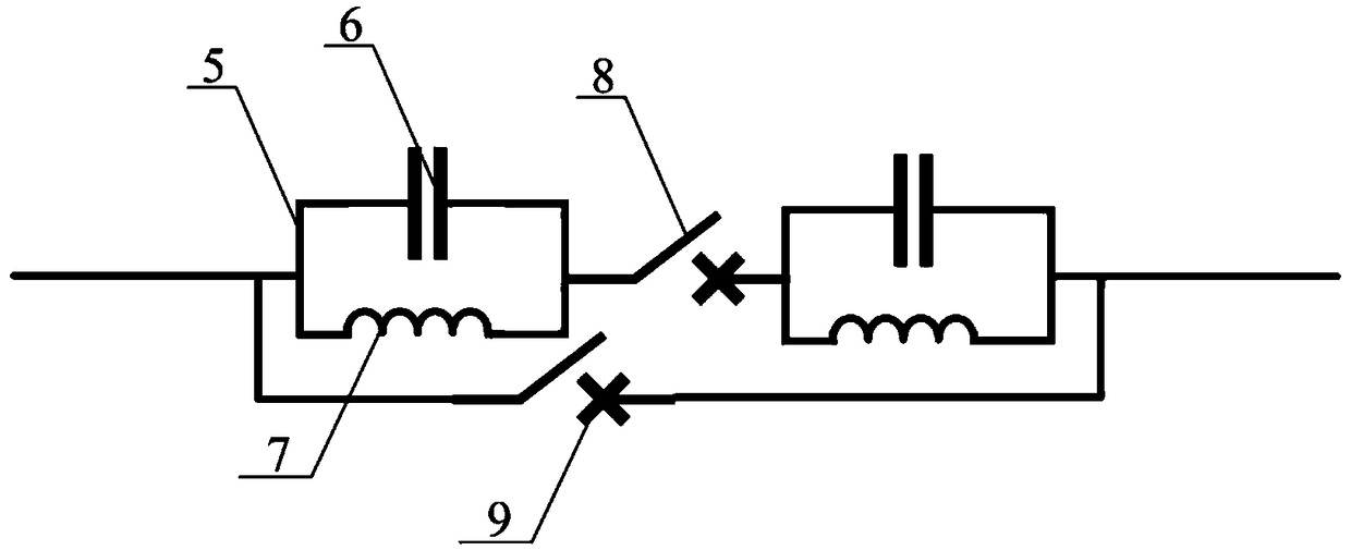
[0065] Example two such as figure 2 As shown, this embodiment is aimed at the wiring method of air circuit breakers (air switches), etc. In order to increase the carrying capacity of the branch circuit of the circuit breaker, a branch circuit is connected in parallel on the basis of the first embodiment, and the branch circuit Connect a secondary circuit breaker 9 in series.

Embodiment 3

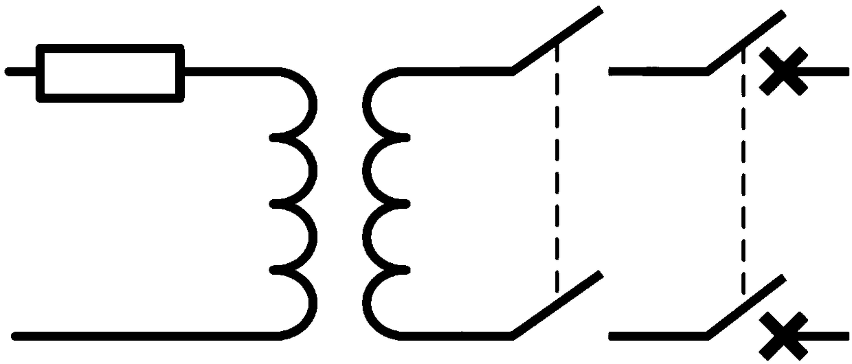
[0066] Embodiment three such as Figure 4 As shown, this embodiment is aimed at the connection mode of the circuit breaker or grounding switch of the transformer, including parallel self-discharge circuit one 19, capacitor gap one 20, inductance coil one 21, circuit breaker one 22, parallel self-discharge circuit two 23, Capacitor gap two 25, inductance coil two 24, circuit breaker two 26. Wherein both ends of the transformer are provided, and two parallel self-discharge circuits are connected in series on each circuit breaker branch, and the positions connected in series of the parallel self-discharge circuits are respectively located before and after the circuit breaker, and the inductance coil It is connected in parallel with the capacitance gap to form a parallel self-discharge circuit, wherein the first circuit breaker 22 and the second circuit breaker 26 operate simultaneously.


PUM


Abstract

The invention discloses an arc extinction device and method capable of being used for alternating-current and direct-current circuit breaker of a power grid. The device comprises a control mechanism,a detecting mechanism and an executing mechanism, and parallel self-discharging loops are arranged in the device; the executing mechanism comprises a circuit breaker; a branch of the circuit breaker is connected with two parallel self-discharging loops in series; the series connection positions of the parallel self-discharging loops are separately positioned in the front and at the rear of the circuit breaker. The energy generated by current mutation is absorbed by the parallel self-discharging loop, and is released through a capacitance gap of the parallel self-discharging loop, arc is stopped, and various problems of arcs in the power grid are solved.

Description

technical field [0001] The invention belongs to the technical field of circuit breakers, and in particular relates to an arc suppression device and method which can be used for AC and DC circuit breakers in power grids. Background technique [0002] When transformers and various electrical equipment are put into or out of the grid, they are all completed by switching appliances. When it is turned off in the atmosphere, as long as the power supply voltage exceeds 12-20V and the cut-off current exceeds 0.25-1A, a mass of extremely high temperature, strong light, and energy will be generated between the contacts (arc gap for short). Conductive approximately cylindrical plasma gas, plasma gas discharge is the arc. [0003] In fact, when the switching device is working, the voltage and current of the circuit are mostly greater than the arc voltage and arc current. That is, the phenomenon that an arc is inevitably generated in the contact gap when the circuit is broken. The gen...

Claims


Application Information

Patent Timeline
Patent Type & Authority Applications(China)
IPC IPC(8): H02H9/08H02H9/04H02H7/22
CPCH02H7/222H02H9/042H02H9/08
Inventor 陈达王雪燕
Owner 王雪燕
Why Eureka
Try Eureka