Display panel and display device

A display panel and area technology, applied in the direction of electrical components, diodes, electric solid devices, etc., can solve the problems of serious moiré in optical modules and affect the display quality, etc., to increase the area, improve light extraction efficiency, and reduce power consumption Effect

Active Publication Date: 2021-07-30
HEFEI VISIONOX TECH CO LTD
View PDF12 Cites 0 Cited by
  • Summary
  • Abstract
  • Description
  • Claims
  • Application Information

AI Technical Summary

Problems solved by technology

However, due to the uniform arrangement of the patterns of each film layer, the moiré pattern in the corresponding area of ​​the optical module is serious, which affects the display quality

Method used


Image

  • Display panel and display device
  • Display panel and display device
  • Display panel and display device

Examples


Embodiment Construction

[0024] The following will clearly and completely describe the technical solutions in the embodiments of the present application with reference to the accompanying drawings in the embodiments of the present application. Obviously, the described embodiments are only part of the embodiments of the present application, not all of them. Based on the embodiments in this application, all other embodiments obtained by persons of ordinary skill in the art without making creative efforts belong to the scope of protection of this application.

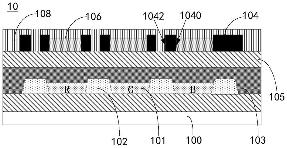
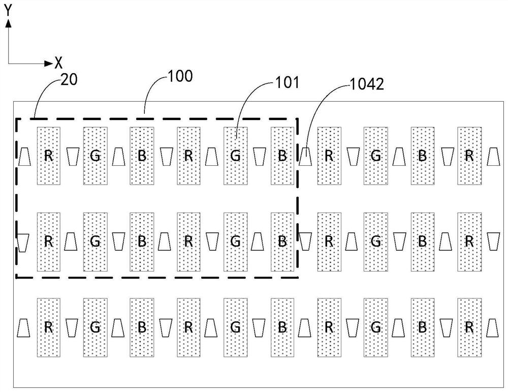
[0025] see figure 1 , figure 1 It is a schematic structural diagram of an embodiment of the display panel of the present application, figure 2 for figure 1 A schematic structural diagram of an embodiment of the orthographic projection of the second via hole and the light emitting unit on the substrate. The display panel 10 provided in the present application may be an OLED display panel, a Micro-OLED display panel, and the like. The display p...


PUM


Abstract

The invention discloses a display panel and a display device. The display panel comprises a substrate, a pixel limiting layer, a shading layer and a plurality of color resistance blocks; the pixel limiting layer is located on one side of the substrate and comprises a plurality of openings, and a light-emitting unit is arranged in each opening; the shading layer is located on the side, away from the substrate, of the pixel limiting layer, and a plurality of first via holes and a plurality of second via holes are formed in the shading layer; the orthographic projections, on the substrate, of the first via holes cover the orthographic projections, on the substrate, of the light-emitting units at the corresponding positions, and the orthographic projections, on the substrate, of the second via holes are located in the orthographic projection, on the substrate, of the pixel limiting layer; the structure of the orthographic projections of at least part of the second via holes on the substrate is different from the structure of the orthographic projections of the adjacent light-emitting units on the substrate, and the different structures comprise different shapes, or the same shape but different angles; and the plurality of color resistance blocks are positioned in the first via holes. In this way, moire patterns of the corresponding area of an optical module can be reduced.

Description

technical field [0001] The present application belongs to the field of display technology, and in particular relates to a display panel and a display device. Background technique [0002] With the continuous development of display technology, OLED (Organic Light Emitting Diode) display panels have attracted widespread attention due to their advantages of low energy consumption, low production cost, self-illumination, wide viewing angle, and fast response speed. [0003] In order to further reduce the thickness of the display panel, improve its flexibility, and at the same time improve the light extraction efficiency and reduce power consumption under the premise of ensuring the contrast ratio, many display panel companies are currently developing COE that replaces the polarizer in the OLED display panel with the color filter CF. (color filter on encapsulation) structure. [0004] Based on the COE structure, the optical modules inside or below the display panel need higher t...

Claims


Application Information

Patent Timeline
Patent Type & Authority Applications(China)
IPC IPC(8): H01L27/32H01L51/52
CPCH10K59/35H10K59/50H10K50/85H10K50/865
Inventor 刘幸一
Owner HEFEI VISIONOX TECH CO LTD
Why Eureka
Try Eureka