Double-layer conjugate bar-type linear motor structure

A linear motor and yoke rod type technology is applied in the structural field of a double-layer conjugate rod type linear motor, which can solve the problems of increased heat generation, large speed fluctuation, and reduced efficiency of the motor, and achieves product cost saving and simple and convenient manufacturing. , the effect of simple structure

Inactive Publication Date: 2019-02-19
宋局
View PDF6 Cites 1 Cited by
  • Summary
  • Abstract
  • Description
  • Claims
  • Application Information

AI Technical Summary

Problems solved by technology

[0003] At present, the cylindrical linear motor has the following defects: the structure of the cylindrical linear motor is difficult, and the processing is difficult, which seriously causes waste of manpower and machinery. The structure of the cylindrical linear motor adopts a horizontal laminated structure. Although the structure is simple and convenient to manufacture, The horizontal combination of the iron core cannot cut off the eddy current circuit, and the eddy current loss is large, which increases the heat generation of the motor and reduces the efficiency. Due to the existence of the longitudinal edge effect of the cylindrical linear motor, especially at low speed operation, the speed fluctuation is large, which seriously affects the positioning accuracy and Repeatability, cylindrical linear motors with the same specifications of ironless motors have a small output, which cannot meet customer demand standards, and a lot of material is wasted. In order to solve the above-mentioned problems, the present invention designs a double-layer conjugate rod linear motor Structure

Method used


Image

  • Double-layer conjugate bar-type linear motor structure
  • Double-layer conjugate bar-type linear motor structure
  • Double-layer conjugate bar-type linear motor structure

Examples


Embodiment Construction

[0019] The following will clearly and completely describe the technical solutions in the embodiments of the present invention with reference to the accompanying drawings in the embodiments of the present invention. Obviously, the described embodiments are only some, not all, embodiments of the present invention. Based on the embodiments of the present invention, all other embodiments obtained by persons of ordinary skill in the art without making creative efforts belong to the protection scope of the present invention.

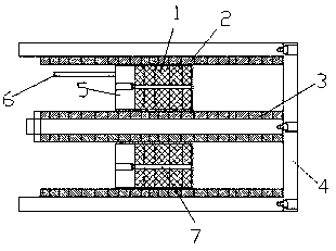
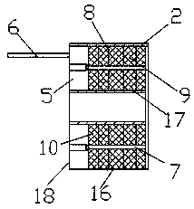
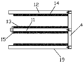
[0020] see Figure 1-3 , the present invention provides a technical solution: including a mover coil 18, a magnetic track 19 and a stator yoke 7, the mover coil 18 includes a coil 1, a skeleton 2, an end cover 5, a stator yoke 7 and a cable 6, and the coil 1 is divided into an inner coil 10 and an outer coil 9, the skeleton 2 is divided into an inner skeleton 16 and an outer skeleton 17, and the magnetic track 19 includes a permanent magnet 13, a permanent mag...


PUM


Abstract

The invention discloses a double-layer conjugate bar-type linear motor structure which comprises a movable coil, a magnetic track and a stator yoke. The movable coil comprises a coil body, a framework, an end cover, a rotor yoke and a cable, the coil includes an inner coil and an outer coil, the framework includes an inner framework and an outer framework, the magnetic track comprises a first permanent magnet, a second permanent magnet, a first rotor yoke, a second rotor yoke and a magnetic track supporting frame, partition pads are arranged in the inner coil and the outer coil, the magnetic track supporting frame is arranged at the right end of the first rotor yoke, and a nut is arranged at the left end of the first rotor yoke. Output of the motor is 1.5 times or more that of a common single-layer tubular linear motor, the structure is simpler, iron loss is basically 0W, the efficiency of the motor is greatly improved, product cost is greatly saved, and positioning accuracy and repeated accuracy of a workpiece are improved.

Description

technical field [0001] The invention relates to the technical field of motors, in particular to a structure of a double-layer conjugate rod linear motor. Background technique [0002] Linear motor is a kind of mechanical energy that directly converts electrical energy into linear motion without any intermediate conversion mechanism. In particular, the cylindrical linear motor adopts two-end support mechanism, which replaces the screw mechanism as much as possible. The linear motor is easy to support the mover with magnetic suspension, so that there is always a certain air gap between the mover and the yoke without contact, which eliminates the contact friction between the mover and the stator, and greatly improves the sensitivity of the transmission system. Quickness and followability. Cylindrical linear motors have outstanding advantages in fields such as oil field and weapon shooting. [0003] At present, the cylindrical linear motor has the following defects: the struc...

Claims


Application Information

Patent Timeline
Patent Type & Authority Applications(China)
IPC IPC(8): H02K41/02
CPCH02K41/02
Inventor 宋局
Owner 宋局
Why Eureka
Try Eureka