Soil crushing device

A crushing and soil technology, applied in grain processing, etc., can solve the problems of dusty, environmental pollution, etc., and achieve the effects of improving environmental protection, reducing dust particles, and facilitating operation

Inactive Publication Date: 2019-02-22
杭州屹泉科技有限公司
View PDF0 Cites 1 Cited by
  • Summary
  • Abstract
  • Description
  • Claims
  • Application Information

AI Technical Summary

Problems solved by technology

[0004] The purpose of the present invention is to provide a soil crushing device to solve the problem that the existing soil crushing ma

Method used


Image

  • Soil crushing device
  • Soil crushing device
  • Soil crushing device

Examples


Example Embodiment

[0021] Example 1

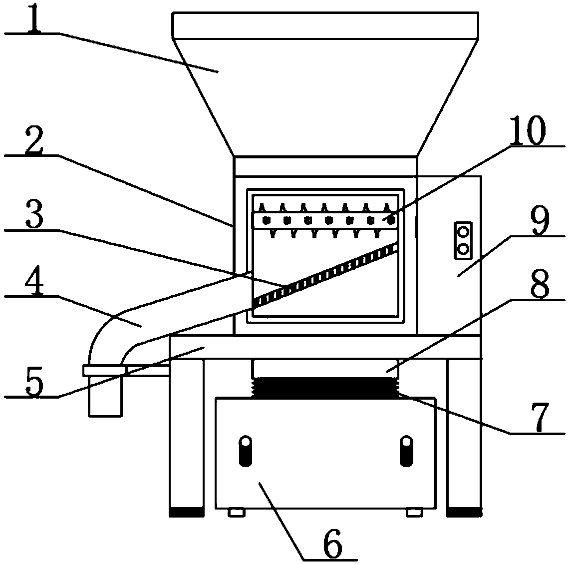
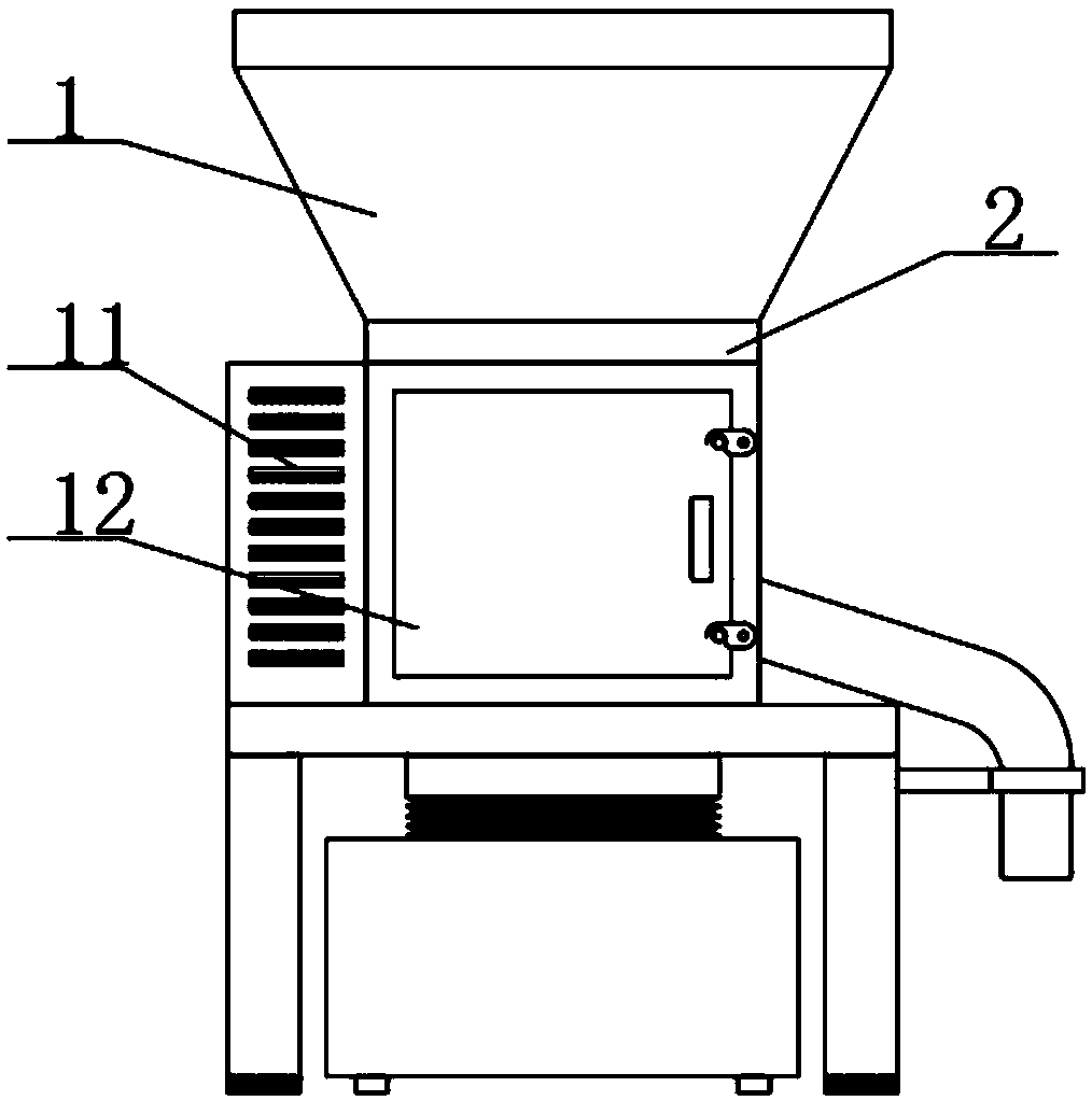
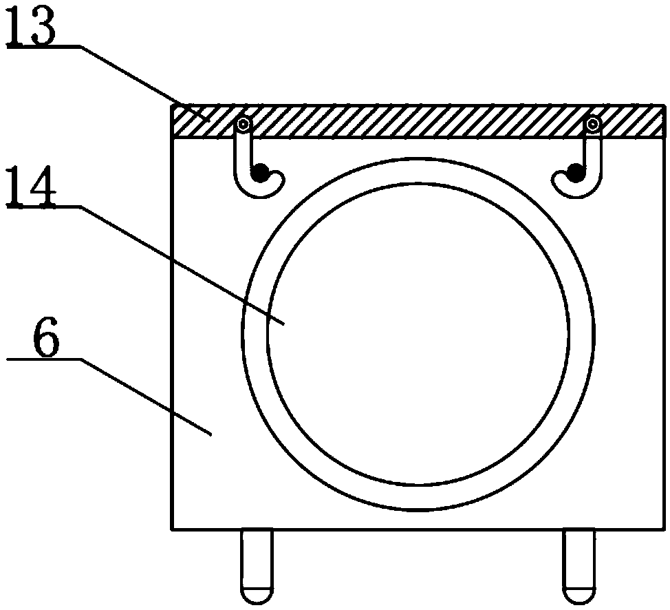
[0022] see figure 1 , figure 2 , image 3 and Figure 4 , the present invention provides a technical solution: a soil crushing device, including a device main body 2, a feeding hopper 1 is provided on the upper end of the device main body 2, a bracket 5 is provided on the lower end, and a first discharge port 4 and a first outlet 4 are respectively provided on both sides. Motor box 9, a servo motor 19 is arranged inside the motor box 9, a running water pipe 15 is arranged around the upper end surface of the hopper 1, and an atomizing nozzle 16 is symmetrically arranged on the inner surface of the hopper 1, and the tap water is sprayed in the form of water mist On the upper end surface of the hopper 1, to prevent dust from raising and causing pollution, the upper end of the main body 2 of the device is provided with intermeshing soil-crushing knives 10, the soil clods are squeezed and broken by the soil-crushing knives 10, and the lower end of the soil-cr...

Example Embodiment

[0026] Example 2

[0027] see figure 1 , figure 2 , image 3 , Figure 4 and Figure 5 , the present invention provides a technical solution: a soil crushing device, including a device main body 2, a feeding hopper 1 is provided on the upper end of the device main body 2, a bracket 5 is provided on the lower end, and a first discharge port 4 and a first outlet 4 are respectively provided on both sides. Motor box 9, a servo motor 19 is arranged inside the motor box 9, a running water pipe 15 is arranged around the upper end surface of the hopper 1, and an atomizing nozzle 16 is symmetrically arranged on the inner surface of the hopper 1, and the tap water is sprayed in the form of water mist On the upper end surface of the hopper 1, to prevent dust from raising and causing pollution, the upper end of the main body 2 of the device is provided with intermeshing soil-crushing knives 10, the soil clods are squeezed and broken by the soil-crushing knives 10, and the lower end o...


PUM


Abstract

The invention discloses a soil crushing device. The soil crushing device comprises a device body, a feeding hopper is arranged on the upper end surface of the device body, a supporting frame is arranged on the lower end face of the device body, a first discharging opening and a motor box are arranged on the two side faces of the device body respectively, a servo motor is arranged in the motor box,a tap water pipe is arranged on the upper end face of the feeding hopper in a surrounding mode, an atomizing nozzle is symmetrically arranged at the upper end of the inner side surface of the feedinghopper, a soil crushing knife which is meshed with each other is arranged at the upper end of the interior of the device body, a sieve plate is arranged at the lower end of the soil crushing knife, asecond discharging opening penetrating through the support is formed in the middle of the bottom end of the device body. According to the device, the atomizing nozzle is arranged, dust particles above the feeding hopper are reduced, so that the environmental protection performance of device is improved, the structure is simple, the operation is convenient, the sieve plate with the spherical rotating part is arranged, so that the vibration of the soil and the separation of fine crushed soil are facilitated, a maintenance door is arranged, so that the device can be conveniently cleaned, and themaintenance of the device is facilitated.

Description

technical field [0001] The invention belongs to the technical field of soil processing equipment, and in particular relates to a soil crushing device. Background technique [0002] The soil crusher is a device for crushing the soil. Generally, a loader is used to pour lumpy loess and other soil into the soil crusher for crushing, and then it is transferred to other locations by a belt conveyor for crushed soil. Generally, they are relatively dry and firm, and will generate more dust when broken, which will have a certain impact on the surrounding environment. [0003] Existing soil crushing machines have the problem of generating more dust during crushing and causing pollution to the environment. For this reason, we propose a soil crushing device. Contents of the invention [0004] The object of the present invention is to provide a soil crushing device to solve the problem that the existing soil crushing machine proposed in the above background technology will generate m...

Claims


Application Information

Patent Timeline
IPC IPC(8): B02C18/14B02C19/16B02C23/16
CPCB02C18/142B02C19/16B02C23/16B02C2023/165
Inventor 周成斌
Owner 杭州屹泉科技有限公司
Why Eureka
Try Eureka