An induction brazing device and welding method for bent pipe joints

A technology of induction brazing and pipe joints, applied in welding equipment, auxiliary devices, tin feeding devices, etc., can solve problems affecting product delivery cycle, poor welding quality, long process, etc., to reduce operation difficulty and improve processing efficiency , the effect of high welding quality

Active Publication Date: 2020-12-01
SHENYANG LIMING AERO-ENGINE GROUP CORPORATION
View PDF5 Cites 0 Cited by
  • Summary
  • Abstract
  • Description
  • Claims
  • Application Information

AI Technical Summary

Problems solved by technology

[0002] There are a large number of bent pipe joints in the pipelines of aero-engines. Flame brazing is generally used when brazing with matching pipe fittings. The efficiency is low, the process is long, and the welding quality is not good, which affects the product delivery cycle.

Method used


Image

  • An induction brazing device and welding method for bent pipe joints
  • An induction brazing device and welding method for bent pipe joints
  • An induction brazing device and welding method for bent pipe joints

Examples


Embodiment Construction

[0018] It should be noted that all directional indications (such as up, down, left, right, front, back...) in the embodiments of the present invention are only used to explain the relationship between the components in a certain posture (as shown in the accompanying drawings). Relative positional relationship, movement conditions, etc., if the specific posture changes, the directional indication will also change accordingly.

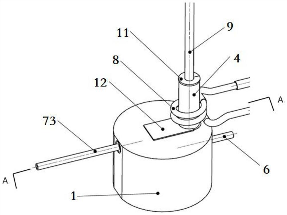
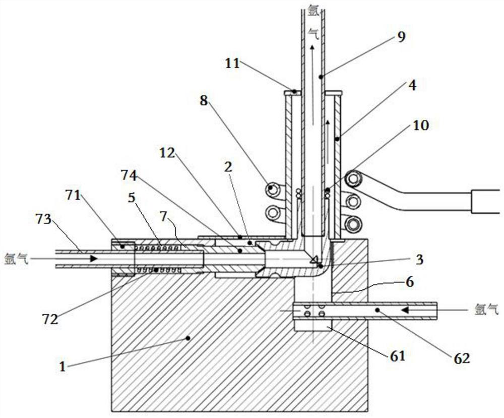
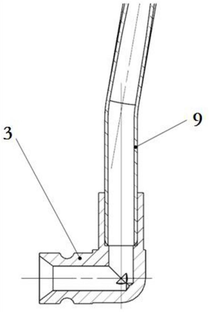
[0019] like Figure 1 to Figure 3 As shown, the present invention provides an induction brazing device for bent pipe joints, including a heat conduction base 1, a first groove 2 is opened on the upper surface of the heat conduction base 1, and a bent pipe joint is placed in the first groove 2 3. The end of the bent pipe joint 3 to be welded extends vertically upward to the top of the heat conduction base 1, and the outer cover of the bent pipe joint 3 to be welded is provided with a high temperature resistant glass tube 4, and the high temperature resist...


PUM


Abstract

The invention discloses an induction brazing device for a bent pipe joint and a welding method thereof. The induction brazing device for the bent pipe joint comprises a heat-conducting base, wherein afirst groove is formed in the upper surface of the heat-conducting base, a bent pipe joint is arranged in the first groove, an end to be welded of the bent pipe joint extends vertically upwards abovethe heat-conducting base, the end to be welded of the bent pipe joint is sleeved with a high-temperature resistant glass tube externally, the high-temperature resistant glass tube is fixedly assembled with the upper surface of the heat-conducting base, and a first argon channel and a second argon channel are arranged in the heat-conducting base. A gas guide pressing mechanism is arranged inside the first argon channel, one end of the air guide pressing mechanism is communicated with an argon source, and the other end of the air guide pressing mechanism is communicated with an inner cavity ofthe bent pipe joint; and one end of the second argon channel is communicated with the argon source, and the other end of the second argon channel is communicated with an inner cavity of the high-temperature-resistant glass tube. The high-temperature-resistant glass tube is sleeved with a high-frequency induction coil externally, a pipeline matched with the bent pipe joint is inserted into an end to be welded of the bent pipe joint, and solder rings are arranged at a joint of the pipeline matched with the bent pipe join and the end to be welded of the bent pipe joint. The induction brazing device for the bent pipe joint and the welding method thereof simplifies the welding process, and improves processing efficiency remarkably and welding quality.

Description

technical field [0001] The invention belongs to the technical field of induction brazing, and in particular relates to an induction brazing device and a welding method for curved pipe joints. Background technique [0002] There are a large number of curved pipe joints in the pipeline of aero-engines. Flame brazing is generally used when brazing with matching pipe fittings. The efficiency is low, the process is long, and the welding quality is not good, which affects the product delivery cycle. Contents of the invention [0003] In order to solve the problems existing in the prior art, the present invention provides an induction brazing device and welding method for bent pipe joints, which can replace traditional flame brazing, significantly improve welding quality and efficiency, and meet product quality and delivery requirements. The technical solution is as follows: [0004] An induction brazing device for bent pipe joints, comprising a heat conduction base, a first gro...

Claims


Application Information

Patent Timeline
Patent Type & Authority Patents(China)
IPC IPC(8): B23K3/08B23K3/06
CPCB23K3/0623B23K3/08
Inventor 乔勇王英刘明刘文博李松
Owner SHENYANG LIMING AERO-ENGINE GROUP CORPORATION
Why Eureka
Try Eureka