Motor and controller integrated system

An integrated system and controller technology, applied in the direction of control drive, connection with control/drive circuit, electromechanical device, etc., can solve the problems of poor cooling effect and motor performance degradation, achieve strong heat dissipation and improve safety The effect of continuous and stable performance and output power

Pending Publication Date: 2019-02-22
INST OF ELECTRICAL ENG CHINESE ACAD OF SCI
View PDF7 Cites 6 Cited by
  • Summary
  • Abstract
  • Description
  • Claims
  • Application Information

AI Technical Summary

Problems solved by technology

[0005] Therefore, the technical problem to be solved by the present invention is that in the integrated system of the motor and the controller in the prior art, the unilateral cooling effect of the controller is not good, which causes the defect of the performance of the motor to decline

Method used


Image

  • Motor and controller integrated system
  • Motor and controller integrated system
  • Motor and controller integrated system

Examples


Embodiment 1

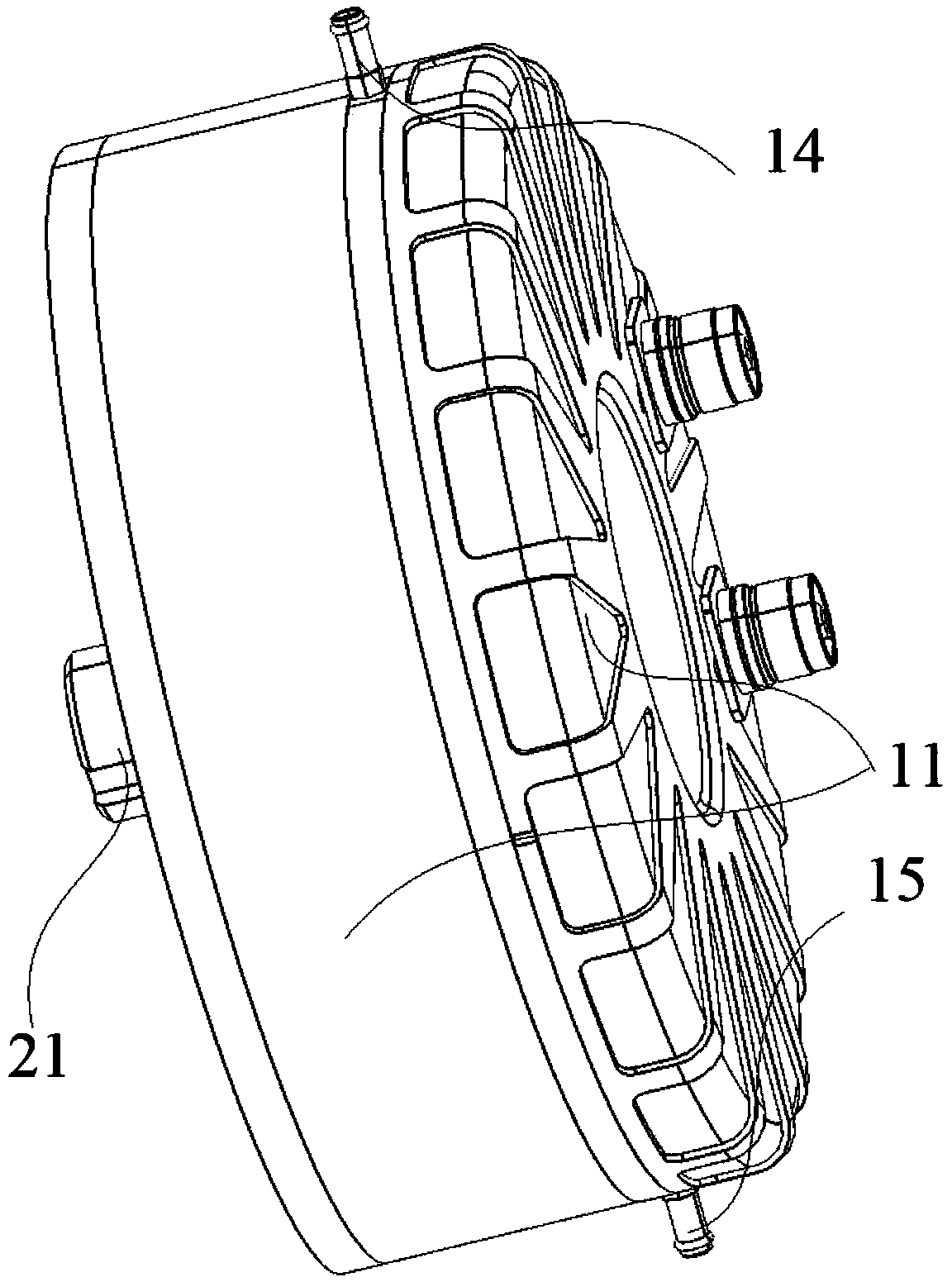
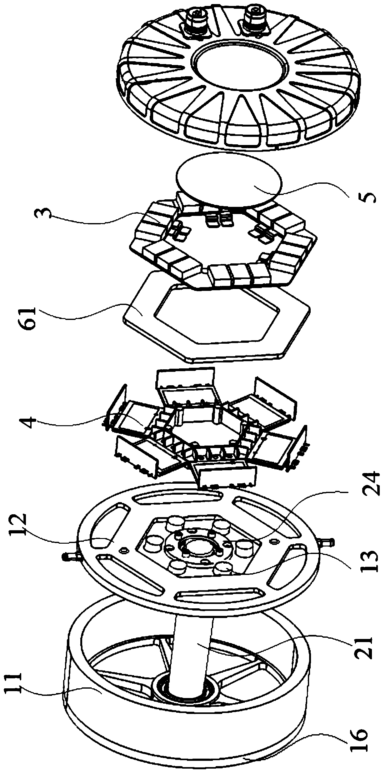
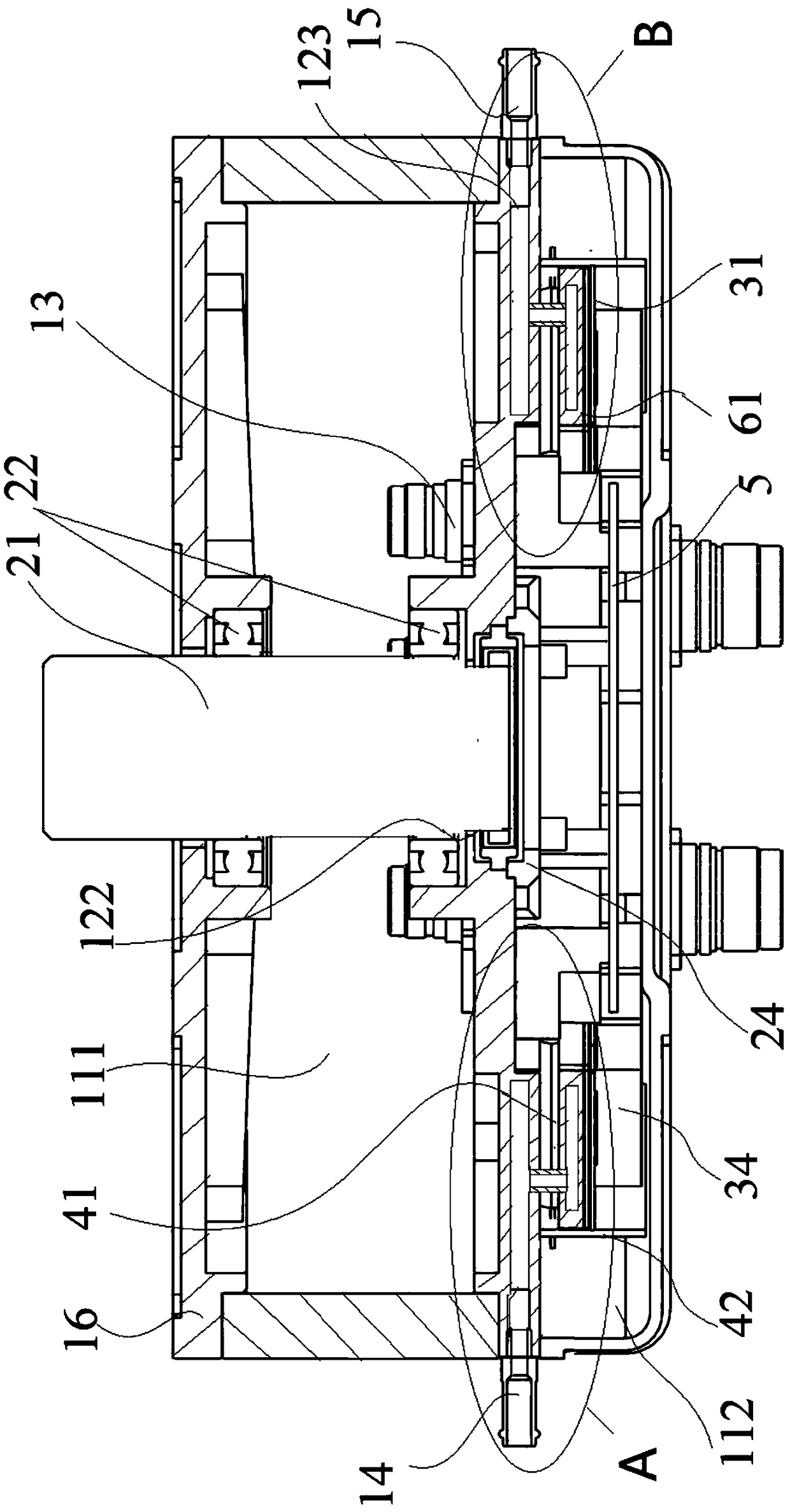
[0064] This embodiment provides an integrated system of a motor and a controller, such as Figure 1 to Figure 9 As shown, it includes: a housing 11, a first end cover 12, a motor body and a controller body. Wherein, the first end cover 12 is arranged in the housing 11, and the inner cavity of the housing 11 is divided into a first cavity 111 and a second cavity 112 with the first end cover 12 as a boundary; the motor body is installed with the first cavity body 111 to convert electrical energy into mechanical energy; the controller body is set in the second cavity 112 to control the action of the motor body.

[0065] like figure 2 and image 3 As shown, the housing 11 includes a second end cover 16 disposed opposite to the first end cover 12 and enclosing a first cavity 111 . As shown in the figure, the motor body has an output shaft 21, a stator (not shown in the figure), a rotor (not shown in the figure) and a coil winding (not shown in the figure).

[0066] Wherein, th...

Embodiment 2

[0088] This embodiment provides an integrated system of a motor and a controller, which differs from the integrated system of a motor and a controller provided in Embodiment 1 in that:

[0089] The power modules 41 can also be three, nine or any multiple of three power modules 41, as long as the power modules 41 are evenly distributed on a circle, in order to cooperate with the commonly used existing three-phase alternating current as the transmission of electric energy Form; at this time, it is ensured that the power modules 41 are evenly distributed on a circle, and at the same time, it is only necessary to ensure that the shape formed by the power conversion assembly 4 adapts to the shape mechanism of the motor body.

[0090] Further, the number of power modules 41 can also be four, five, seven or more, as long as the power modules 41 can be realized as a control source for power output, and convert the direct current input from the input terminal into alternating current ,...

Embodiment 3

[0093] This embodiment provides an integrated system of a motor and a controller, which differs from the integrated system of a motor and a controller provided in Embodiment 1 or Embodiment 2 in that:

[0094] Without considering the number of installed power modules 41 and the influence of the overall shape of the controller body, one, two, three or more power modules 41 can be installed. At this time, it is not necessary to ensure whether the power modules 41 Evenly distributed on the same circle, as long as the connection relationship between the power module 41 , the driving board 42 and the control board 5 is properly ensured.


PUM


Abstract

The invention discloses a motor and controller integrated system. The motor and controller integrated system comprises a shell, a first end cover, a motor body, a controller body and heat dissipationcomponents. The first end cover is arranged in the shell. An inner cavity of the shell is divided into a first cavity and a second cavity with the first end cover as the boundary. The first end coveris internally provided with first heat dissipation channels. The motor body is arranged in the first cavity. The controller body is arranged in the second cavity. The integrated system is provided with capacitance assemblies and power conversion assemblies, wherein the capacitance assemblies and the power conversion assemblies are sequentially arranged in a superposed manner from the direction away from the first end cover to the direction close to the first end cover and electrically connected. All the capacitance assemblies are located on the same layer. All the power conversion assemblies are located on the same layer. The heat dissipation components are arranged between the capacitance assemblies and the power conversion assemblies in a clamped manner and provided with second heat dissipation channels. Direct heat dissipation is conducted on the capacitance assemblies and the power conversion assemblies; indirect conduction conducted through other electronic elements is not needed;the heat dissipation effect achieved among the assemblies is particularly good; and high stability of the outputable power of the motor and controller integrated system is guaranteed.

Description

technical field [0001] The invention relates to the technical field of electric vehicles, in particular to an integrated control system of a motor and a controller. Background technique [0002] In recent years, the development of new energy electric vehicles has become increasingly mature, and the state has increased support for the electric vehicle industry, which has promoted the rapid development of electric vehicles, and at the same time promoted the early entry of electric vehicle products into the lives of ordinary people. One of the cores of the electric vehicle industry is the electric drive system. As a key component of the electric drive system of electric vehicles, the motor controller controls the motor to work according to the set direction, speed, angle and response time through the active operation of the integrated circuit; Become the research focus of the current automotive technology and sustainable development of the automotive industry. [0003] In the ...

Claims


Application Information

Patent Timeline
Patent Type & Authority Applications(China)
IPC IPC(8): B60K1/00B60L15/20H05K7/20
CPCH02K5/20H02K9/19H02K11/30H02K11/33Y02T10/72
Inventor 邰翔范涛温旭辉
Owner INST OF ELECTRICAL ENG CHINESE ACAD OF SCI
Why Eureka
Try Eureka