Lens feeding device capable of controlling force

A feeding device and lens technology, applied in the direction of conveyor control devices, conveyors, conveyor objects, etc., can solve the problems of low force control precision, easily damaged workpieces, poor stability, etc., achieve high control precision and reduce damage rate , the effect of improving applicability

Pending Publication Date: 2019-02-22
珠海市硅酷科技有限公司
View PDF0 Cites 0 Cited by
  • Summary
  • Abstract
  • Description
  • Claims
  • Application Information

AI Technical Summary

Problems solved by technology

[0003] In order to solve the technical problems of low force control precision, poor stability, and easy damage to workpieces in the existing camera module feeding mechanism, the present invention provides a lens feeding device with controllable force

Method used


Image

  • Lens feeding device capable of controlling force

Examples


Embodiment Construction

[0015] The following will clearly and completely describe the technical solutions in the embodiments of the present invention. Obviously, the described embodiments are only some of the embodiments of the present invention, rather than all the embodiments. Based on the embodiments of the present invention, all other embodiments obtained by persons of ordinary skill in the art without making creative efforts belong to the protection scope of the present invention.

[0016] Specific embodiments of the present invention will be described below in conjunction with the accompanying drawings.

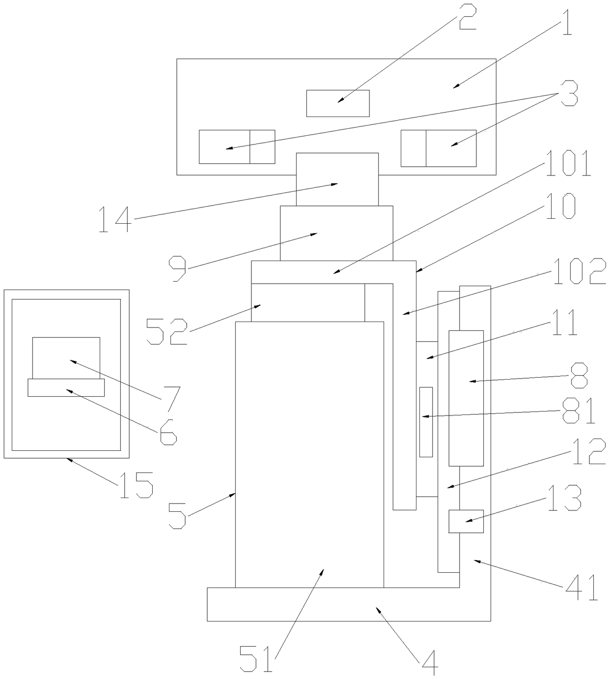
[0017] attached figure 1 It shows a controllable force lens feeding device, which includes a clamping seat 1 provided with an upper limit block 2 and jaws 3, and also includes a base 4, a voice coil motor 5, an encoder 8 and all installed on the electrical control The servo driver 6 and the controller 7 in the cabinet 15, the base 4 is arranged directly below the upper limit block 2, the voic...


PUM


Abstract

The invention relates to a lens feeding device capable of controlling force. The lens feeding device comprises a clamping seat provided with an upper limiting block and a clamping jaw and further comprises a base, a voice coil motor, an encoder, a servo driver and a controller, wherein the base is arranged right below the upper limiting block; the voice coil motor and the encoder are fixedly arranged on the base and are in circuit connection with the servo driver; the servo driver is in circuit connection with the controller; the motor stator of the voice coil motor is fixed on the base; a workpiece placement seat is arranged at the top end of the motor rotor of the voice coil motor; an induction component of the encoder is fixedly connected with the motor rotor; and a sliding mechanism isarranged between the voice coil motor and the base. The lens feeding device is compact, small and exquisite in structural design, precisely controls workpiece impact force through controlling the movement speed of the motor rotor by stages, enlarges the control range, improves the feeding stability, reduces the damage rate and improves the applicability.

Description

technical field [0001] The invention relates to the technical field of lens feeding, in particular to a lens feeding device with controllable force. Background technique [0002] In the mobile phone camera module assembly equipment, it is necessary to assemble the cmos sensor and the lens according to the appropriate position and angle. During assembly, the lens module needs to be translated to the right below the lens gripper, and then raised to withstand the upper limit. Then the jaws clamp the lens module. The upper limit block can ensure that the lens is accurate in height, position and direction, and it is level. However, it requires force to withstand the upper limit block. If the force is too large, the lens module will be damaged. The traditional technology often achieves up and down movement through cylinders or ball screws, and force control through air pressure, springs, etc.; the up and down movement of the cylinder cannot accurately control the speed, accelerati...

Claims


Application Information

Patent Timeline
Patent Type & Authority Applications(China)
IPC IPC(8): B65G47/90B65G43/08
CPCB65G47/90B65G43/08B65G2201/0214B65G2203/042
Inventor 汤毅韬李钦
Owner 珠海市硅酷科技有限公司
Why Eureka
Try Eureka