
Movable type connecting device for reverse construction method steel tube column and reinforcement cage

A connection device and steel pipe column technology, which is applied in water conservancy projects, artificial islands, sheet pile walls, etc., to achieve the effects of convenient operation, simple construction and high operation accuracy

Pending Publication Date: 2019-02-22
昆明捷程桩工有限责任公司
View PDF1 Cites 2 Cited by
  • Summary
  • Abstract
  • Description
  • Claims
  • Application Information

AI Technical Summary

Problems solved by technology

[0005] The purpose of the present invention is to overcome the defects of the prior art and traditional construction equipment, and provide a movable connection device between steel pipe (structure) columns and steel cages in the underground space development method. The device has high operation accuracy and is easy to operate. It can be constructed with or without groundwater, which can solve the connection, hoisting and placement of steel pipe (structure) columns and steel cages, and facilitate the adjustment and positioning of the verticality of the steel pipe (structure) column center during the placement process

Method used


Image

  • Movable type connecting device for reverse construction method steel tube column and reinforcement cage
  • Movable type connecting device for reverse construction method steel tube column and reinforcement cage
  • Movable type connecting device for reverse construction method steel tube column and reinforcement cage

Examples


Embodiment Construction

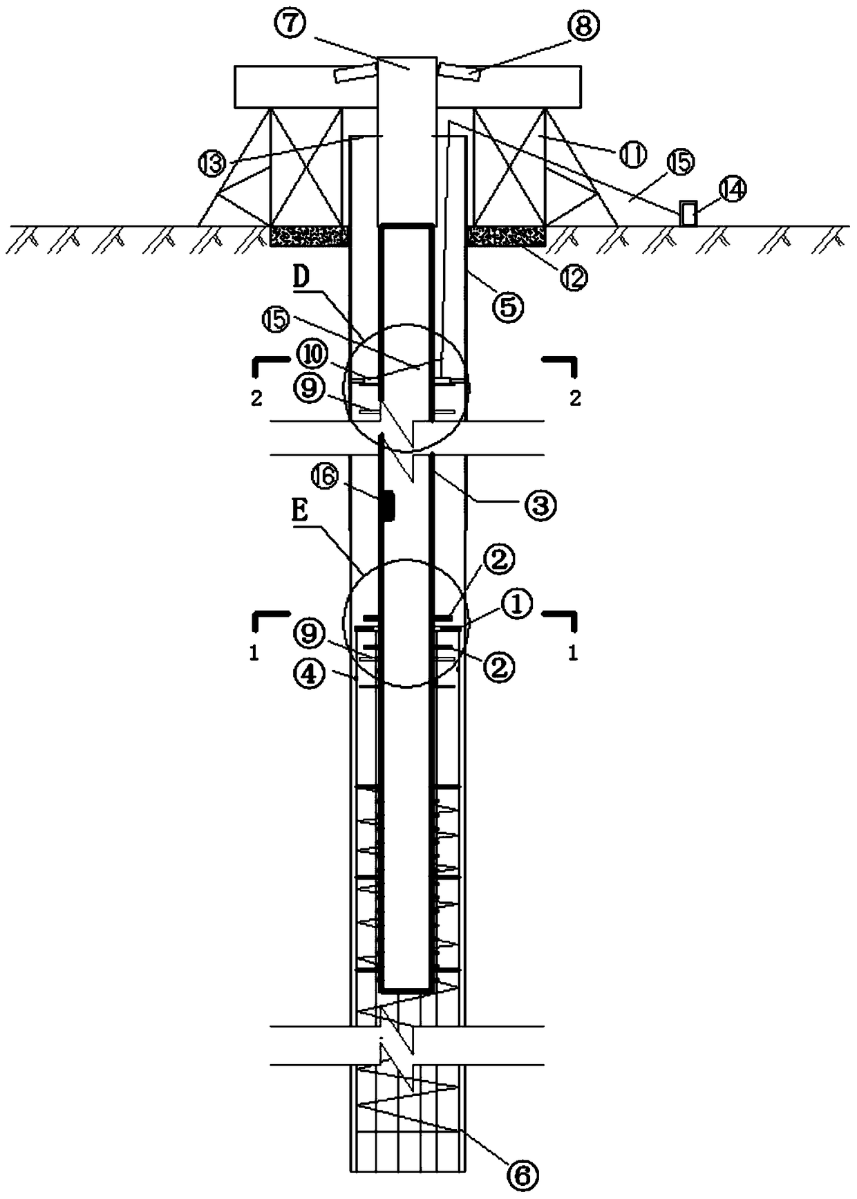
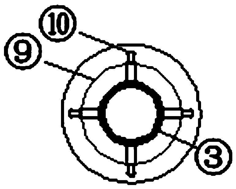
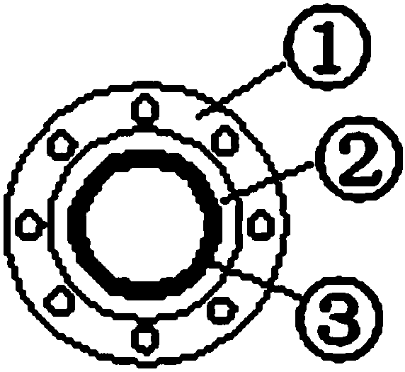
[0018] Referring to each figure, the upper part of the reinforcement cage 6 is fixed with a reinforcement sleeve 4, and the upper port of the reinforcement sleeve 4 is fixed with a front guard plate 1 with a middle hole, and the steel pipe column 3 passes through the middle hole in the middle part of the front guard plate 1, so that the two The connection of the former is suspended and limited. The upper outer wall of the steel pipe column 3 is fixed with a pair of spaced upper and lower limit plates 2. The front guard plate 1 is located between the upper and lower limit plates 2 and the center of the front guard plate 1 The size of the hole is smaller than the diameter of the upper and lower limit plates, and the reinforcement cage 6 and the reinforcement sleeve 4 are located in the all-steel casing 5 in the construction state. In the adjustment state, the reinforcement sleeve 4 of the reinforcement cage 6 can have a certain radial adjustment gap in the all-steel casing 5; the...


PUM


Abstract

The invention discloses a movable type connecting device for a reverse construction method steel tube column and a reinforcement cage, belongs to the an engineering device of the underground space development reverse construction method foundation pit engineering field, and particularly relates to a movable type connecting device for the steel tube (structure) column and the reinforcement cage. The movable type connecting structure is characterized in that a reinforcement sleeve is fixedly arranged on the upper part of the reinforcement cage, wherein the upper port of the reinforcement sleeveis fixedly equipped with a protecting aligning plate with a middle hole; the steel tube column passes through the middle hole of the protecting aligning plate; a pair of upper and lower spaced limiting plates is fixedly arranged on the outer wall of the upper part of the steel tube column; the protecting aligning plate is positioned between upper and lower limiting plates, and the dimension of themiddle hole of the protecting aligning plate is smaller than diameters of the upper and lower limiting plates; and the reinforcement cage and the reinforcement sleeve are positioned in an all-steel protective barrel in a construction state. The movable type connecting device is simple in structure, is high in operation precision, is convenient to operate, and can realize construction in a pile hole with or / without underground water, so that connecting, hoisting and mounting of the steel tube (structure) column and the reinforcement cage can be solved, and regulating and positioning for perpendicularity in a steel tube (structure) column core mounting process are also convenient.

Description

technical field [0001] The invention belongs to the engineering device in the field of underground space development reverse method foundation pit engineering, and specifically relates to a movable connection device between a steel pipe (structure) column and a steel cage. Background technique [0002] In recent years, more and more reverse construction methods have been adopted in the development of ultra-deep underground spaces. The construction of the foundation pit is reversed, that is, the foundation pit support wall is first constructed along the sideline of the basement of the building or around the foundation pit, and the engineering piles and column piles inside the foundation pit are constructed at the same time, and then the top floor of the basement is constructed as a horizontal support, and then layer by layer Excavate the earthwork and pour the underground structure of each layer until the base plate is sealed. The reverse construction method has the advantag...

Claims


Application Information

Patent Timeline
Patent Type & Authority Applications(China)
IPC IPC(8): E02D29/045E02D17/04E02D13/00
CPCE02D13/00E02D17/04E02D29/045
Inventor 刘富华吕夏平陈永庆周家书郭兴明
Owner 昆明捷程桩工有限责任公司
Learn More