Self-adaptive damping piston and damper

A damping piston, self-adaptive technology, applied in the field of mechanical spare parts, can solve problems such as the inability to adjust the damping value, and achieve the effect of wide industrial value

Active Publication Date: 2019-02-22
深圳市无疆智创科技有限公司
View PDF5 Cites 4 Cited by
  • Summary
  • Abstract
  • Description
  • Claims
  • Application Information

AI Technical Summary

Problems solved by technology

The adaptive damping piston in the prior art only has a through hole, and the flow rate of the oil in the through hole is uniform, and the damping value cannot be adjusted

Method used


Image

  • Self-adaptive damping piston and damper
  • Self-adaptive damping piston and damper
  • Self-adaptive damping piston and damper

Examples


Embodiment 1

[0038] like Figure 1-3 .

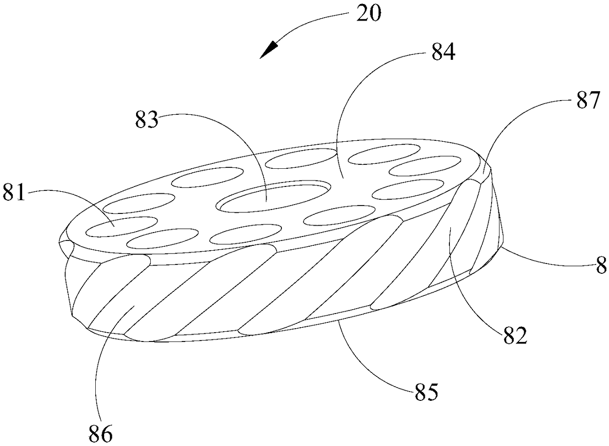
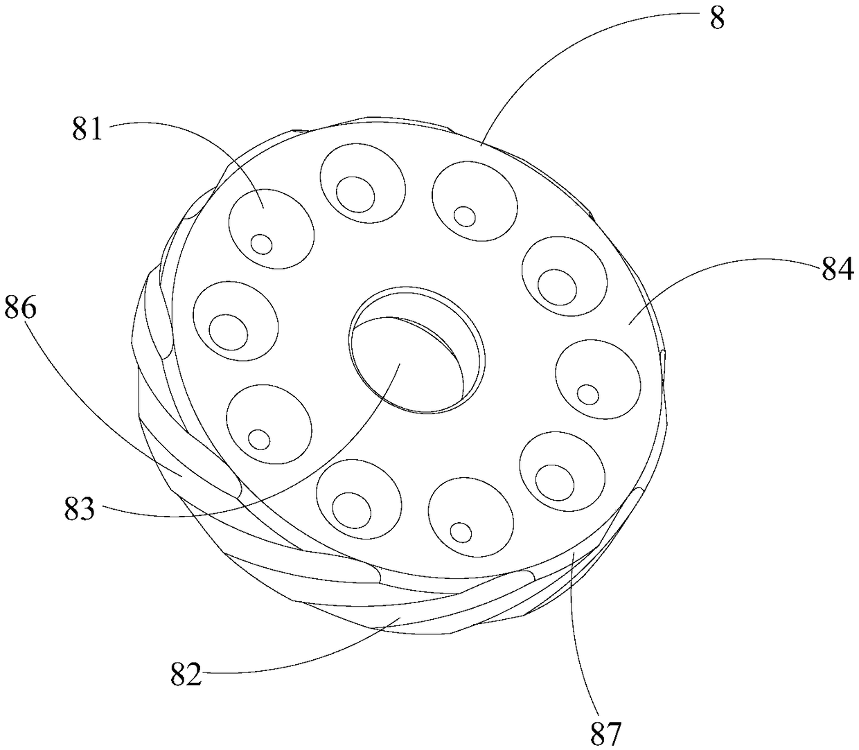
[0039] An adaptive damping piston 20, which includes a piston body 8, the piston body 8 is a cylinder including side surfaces, an upper bottom surface 84 and a lower bottom surface 85, the upper bottom surface 84 and the lower bottom surface 85 are parallel to each other, the The piston body 8 includes a plurality of piston through holes 81 passing through the upper bottom surface 84 and the lower bottom surface 85, and the side surface is provided with a plurality of piston spiral grooves 82, and the two ends of each piston spiral groove 82 are respectively arranged on The upper bottom surface 84 and the lower bottom surface 85 .

[0040] As mentioned above, the self-adaptive damping piston 20 may include a piston body 8, and the piston body 8 is in the shape of a cylinder, specifically, it may be a cylinder or a regular polygon. The piston body 8 includes an upper bottom surface 84 and a lower bottom surface 85 parallel to each other, and there ...

Embodiment 2

[0058] like Figure 1-3 .

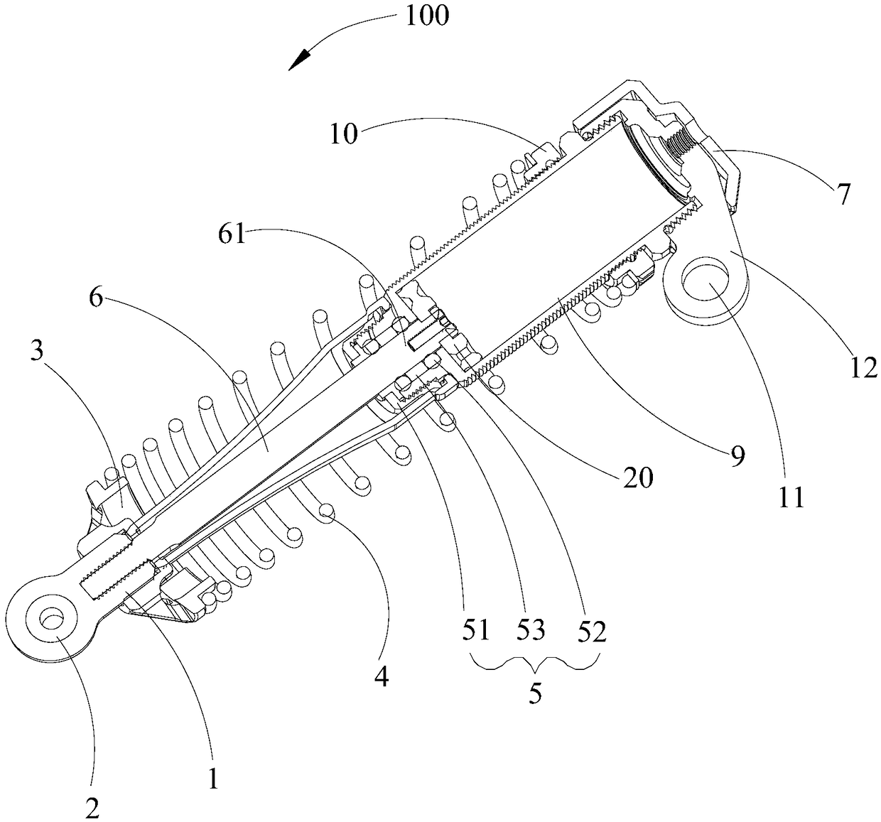
[0059] The shock absorber 100 includes any one of the adaptive damping pistons 20 mentioned above, and the adaptive damping piston 20 is installed on the compression end 61 of the piston rod 14 inside the piston cylinder 9 .

[0060] The above means that the shock absorber 100 of this embodiment includes the adaptive damping piston 20 of the first embodiment. The self-adaptive damping piston 20 is installed in the piston rod 6, the piston rod 6 includes a connection end exposed to the piston barrel 9 and used to connect the fisheye bearing 2, the piston rod 6 also includes a connecting end arranged in the piston barrel 9, and connected to the self-adaptive damping piston 20. Adapt to the compression end 61 of the damping piston 20 for compressing the damping oil.

[0061] Specifically, the adaptive damping piston 20 may include a piston body 8, and the piston body 8 is in the shape of a cylinder, specifically, may be a cylinder or a regular polygo...


PUM


Abstract

The invention discloses a self-adaptive damping piston. The self-adaptive damping piston comprises a piston body, wherein the piston body is a column body comprising a side surface, an upper bottom surface and a lower bottom surface; the upper bottom surface and the lower bottom surface are parallel to each other, the piston body comprises a plurality of piston through holes penetrating through the upper bottom surface and the lower bottom surface, a plurality of piston spiral grooves are formed in the side surface, and the two ends of each piston spiral groove are arranged on the upper bottomsurface and the lower bottom surface respectively. Therefore, the damping oil can pass through the piston through holes and the piston spiral grooves, the spiral grooves of the piston is provided with a spiral degree, so that when the damping stroke is rapidly compressed, the damping oil is strong in pressure when passing through the piston spiral grooves, under the condition that the cross section of the spiral grooves is not changed, the pressure of the damping oil is increased through the pressure intensity of the piston spiral grooves, and the damping value is large; when the damping andcompression are slow, due to the fact that the pressure of the damping oil in the piston spiral grooves is small and the resistance of the bent piston spiral grooves is reduced, and the damping valueis small. Therefore, the self-adaptive damping piston and a damper with same are capable of automatically adjusting the damping value according to the compression force.

Description

technical field [0001] The invention relates to the technical field of mechanical spare parts, in particular to an adaptive damping piston and a shock absorber. Background technique [0002] Adaptive damping pistons are usually used in shock absorbing and energy absorbing devices, especially shock absorbers. The adaptive damping piston in the prior art is only provided with a through hole, and the flow velocity of the oil in the through hole is uniform, and the damping value cannot be adjusted. Contents of the invention [0003] In view of this, the purpose of the self-adaptive damping piston and shock absorber of the present invention is to provide an self-adaptive damping piston and shock absorber capable of automatically adjusting the damping value. [0004] Specifically, the present invention proposes the following specific embodiments: [0005] An adaptive damping piston, which includes a piston body, the piston body is a cylinder including a side surface, an upper ...

Claims


Application Information

Patent Timeline
Patent Type & Authority Applications(China)
IPC IPC(8): F16F9/16F16F9/32F16F9/36
CPCF16F9/16F16F9/3214F16F9/3228F16F9/3235F16F9/362F16F2222/12F16F2238/04
Inventor 袁宝
Owner 深圳市无疆智创科技有限公司
Why Eureka
Try Eureka