Locating clamping mechanism applied to columnar load

A positioning and clamping mechanism, columnar technology, applied in the field of testing, to reduce the moment of inertia, improve efficiency, and save costs

Pending Publication Date: 2019-02-22
CHINA PRECISION ENG INST FOR AIRCRAFT IND AVIC
View PDF6 Cites 5 Cited by
  • Summary
  • Abstract
  • Description
  • Claims
  • Application Information

AI Technical Summary

Problems solved by technology

[0005] The technical problem solved by the present invention is: the prior art cannot realize the high-precision positioning and clamping of the same clamping device for multi-type columnar loads

Method used


Image

  • Locating clamping mechanism applied to columnar load
  • Locating clamping mechanism applied to columnar load
  • Locating clamping mechanism applied to columnar load

Examples


Embodiment Construction

[0019] Specific embodiments of the present invention will be discussed in detail below in conjunction with the accompanying drawings.

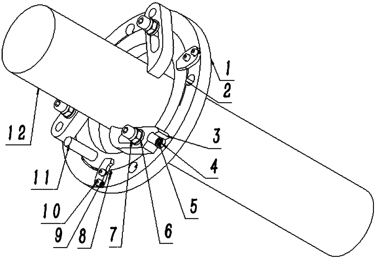
[0020] Such as figure 1 As shown, a positioning and clamping mechanism applied to columnar loads is fixed on the equipment, and the clamping mechanism is used for fixing between the load and the equipment.

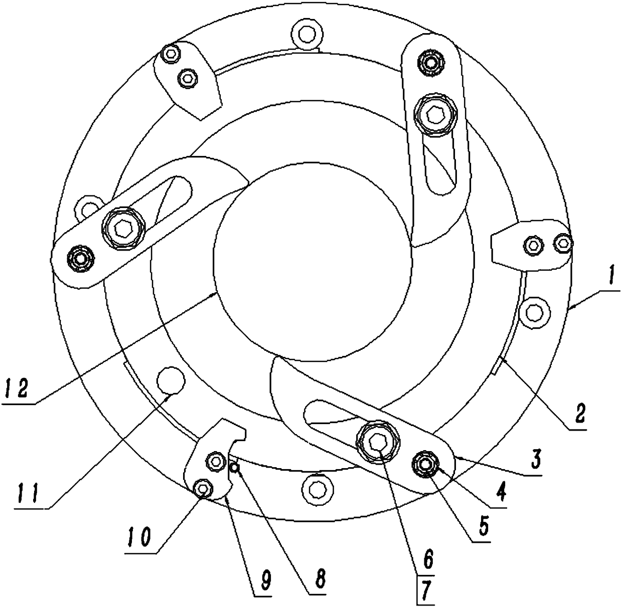
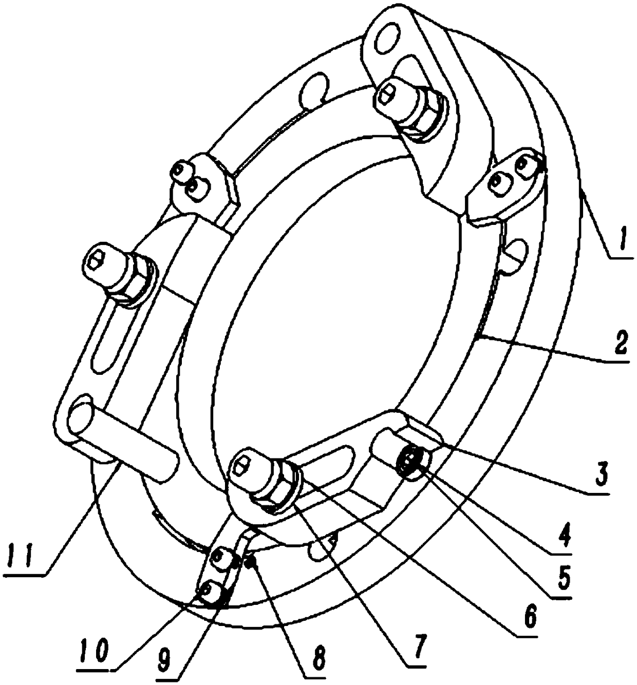
[0021] Such as figure 2 As shown, a positioning and clamping mechanism applied to columnar loads, the mechanism fixes the fixed outer ring (1) on the equipment through the threaded hole, extends the load into the rotating inner ring (2), and rotates the rotating handle (11 ), driving the rotation of the rotating inner ring (2), the rotating column (6) fixed on the rotating inner ring (2) rotates at the same time, sliding in the strip chute (13) of the strip centering claw (3), Drive the strip-shaped centering claw (3) to take the centering shaft (5) installed with the centering bearing (4) as the axis, and close inward to realize the ch...


PUM


Abstract

The invention provides a locating clamping mechanism applied to a columnar load. A three-jaw centering structure is adopted for the locating clamping mechanism. An inner ring and an outer ring rotateto drive three-jaw centering, two-stage locking is arranged, and then clamping requirements of multiple models of products are met. The clamping structure has the characteristics of being simple in structure, small in weight, small in occupied space, high in clamping precision and high in stability.

Description

technical field [0001] The invention relates to the technical field of testing, in particular to a clamping mechanism. Background technique [0002] The clamping mechanism is mainly used in the load clamping of the simulated turntable equipment for testing the performance of the missile and performing the attitude motion simulation (simulation) test of the carrier. The measured target is usually a columnar metal. Due to the high-speed rotation of the measured target and the characteristics of numerous models, the simulation turntable requires high-precision and high-stability mechanical locking, automatic centering, and continuous clamping to adapt to various types of missiles and components. Test and use needs. [0003] In the simulation test, the tested components often have many different models and sizes, and the test needs to meet the characteristics of high precision, high stability, high load capacity, small footprint, small weight and simple structure. However, the...

Claims


Application Information

Patent Timeline
Patent Type & Authority Applications(China)
IPC IPC(8): F42B35/00B25B11/00
CPCF42B35/00B25B11/00
Inventor 张馨月陈自悟程亚静
Owner CHINA PRECISION ENG INST FOR AIRCRAFT IND AVIC
Why Eureka
Try Eureka