
Ultrasonic transducer with cooling device

A technology of cooling devices and transducers, which is applied in the direction of household refrigeration devices, sound-generating devices, instruments, etc., can solve the problems of difficult mass production and use, complex structure, expensive price, etc., and achieve efficient and rapid cooling, reasonable and simple structure, and production low cost effect

Inactive Publication Date: 2019-02-22
SBT ULTRASONIC TECH CO LTD
View PDF0 Cites 4 Cited by
  • Summary
  • Abstract
  • Description
  • Claims
  • Application Information

AI Technical Summary

Problems solved by technology

At present, the general practice is to use compressed air for cooling, and directly connect the compressed air to the transducer shell, which can better solve the problem of transducer cooling, but this method has higher requirements for compressed air, and it needs to be dry and clean. Air source, it is inconvenient to use in the case of no air source
In addition, there is also a transducer design using a liquid cooling system, but this method has a complex structure, difficult processing, and is expensive, making it difficult to mass-produce and use.

Method used


Image

  • Ultrasonic transducer with cooling device

Examples


Embodiment Construction

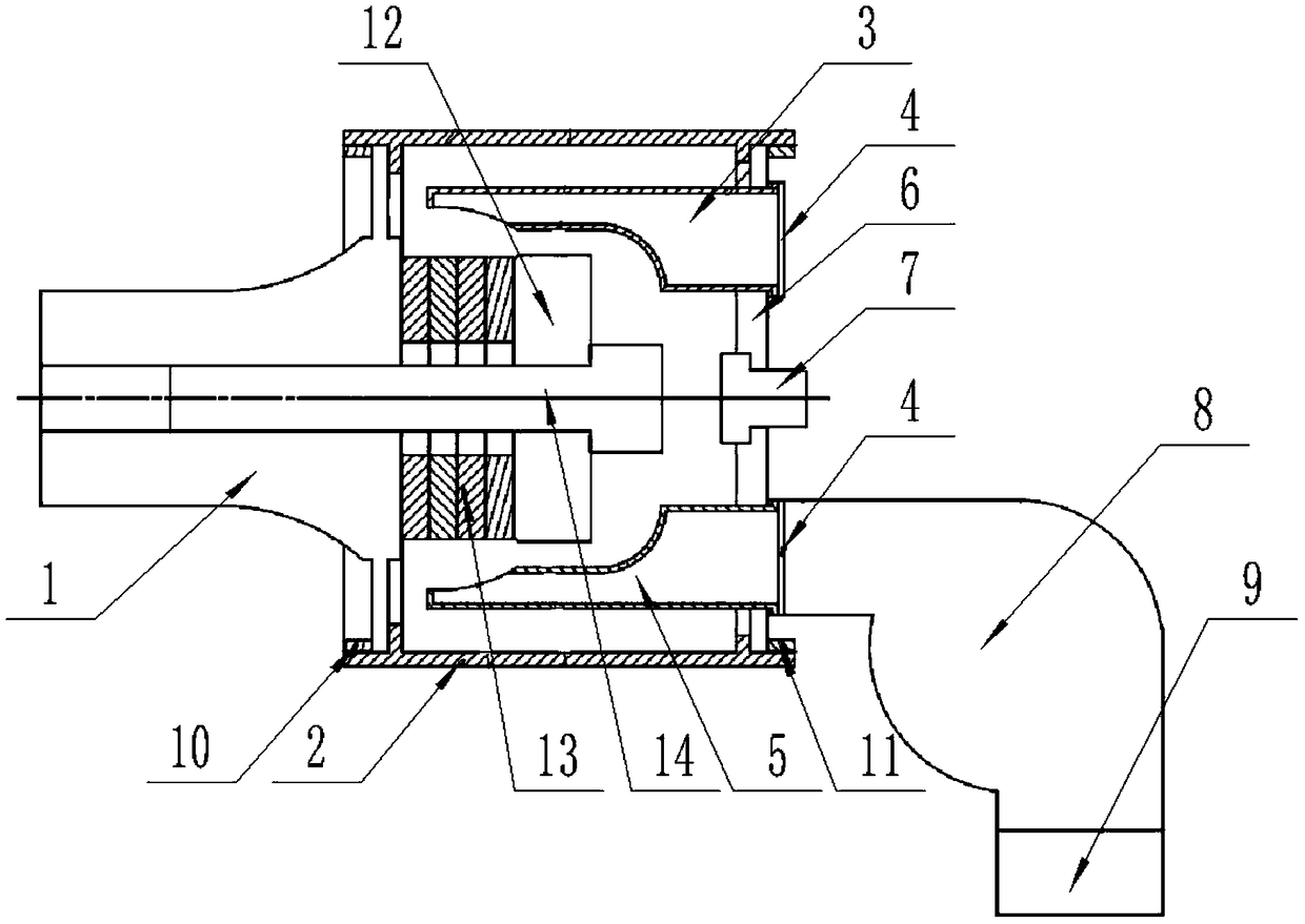
[0015] Such as figure 1 As shown, this specific embodiment adopts the following technical solutions: an ultrasonic transducer with a cooling device, including a transducer vibrator 1 and a transducer housing 2, and also includes an air outlet pipe 3, a dust-proof filter screen 4, and an air intake pipe 5. Transducer rear cover 6, connector 7, fan 8, drying box 9, first sealing ring 10, second sealing ring 11, cover plate 12, piezoelectric ceramics 13 and prestressed bolts 14; the transducer The vibrator 1 is fixedly connected to the left end of the transducer housing 2, and the connection between the transducer vibrator 1 and the transducer housing 2 is provided with a first sealing ring 10; the piezoelectric ceramic 13 and the cover plate 12 are prestressed The bolt 14 is fixedly connected to the right side of the transducer vibrator 1, the piezoelectric ceramic 13 is located on the left side of the cover plate 12; the transducer rear cover 6 is fixedly connected to the right...


PUM


Abstract

The invention discloses an ultrasonic transducer with a cooling device. The ultrasonic transducer is provided a blower fan and air inlet and outlet ducts, the air ducts extend to position near an oscillator piezoelectric ceramics crystal pile of the transducer, the blower fan generates high speed airflow, the air inlet and output ducts form high-speed convection near the piezoelectric ceramics, heat generated during work of the energy transducer is taken away, and cooling is efficient and rapid; and ports of the blower fan and air inlet and outlet ducts are provided with dustproof filtering screens and drying boxes to realize waterproof and dustproof effects, and long-term operation of the cooling device is ensured. The energy transducer is simple and reasonable in structure, low in the production cost, convenient to install and complete in functions, high-efficiency cooling of the energy transducer can be realized needless of an outside air source, and it is ensured that the energy transducer can work stably for long time under a high power condition.

Description

technical field [0001] The invention relates to the technical field of ultrasonic transducers, in particular to an ultrasonic transducer with a cooling device. Background technique [0002] Because ultrasonic waves will produce many physical, chemical and biological effects when propagating in media, ultrasonics is widely used in industry, agriculture, biomedicine and other fields. Ultrasonic applications generally use ultrasonic transducers to convert alternating electrical energy into ultrasonic vibrations within the ultrasonic frequency range to achieve energy conversion. Due to the certain consumption of the ultrasonic transducer during the energy conversion process, the specific performance is that the transducer vibrator will generate heat, especially under long-term high-power working conditions, which directly affects the performance of the transducer and even causes damage. Therefore, the heat dissipation of the transducer must be considered in high-power ultrasoni...

Claims


Application Information

Patent Timeline
Patent Type & Authority Applications(China)
IPC IPC(8): G10K9/122F25D1/00
CPCG10K9/122F25D1/00
Inventor 周宏建左斌石新华段忠福
Owner SBT ULTRASONIC TECH CO LTD
Learn More