
Novel dry transformer

A dry-type transformer, a new type of technology, applied in the field of transformers, can solve problems such as aging of components in the transformer, safety accidents, and reduced service life, and achieve the effects of avoiding structural stability, improving work efficiency, and reducing noise

Inactive Publication Date: 2019-02-22
四川星脉电子科技有限责任公司
View PDF0 Cites 0 Cited by
  • Summary
  • Abstract
  • Description
  • Claims
  • Application Information

AI Technical Summary

Problems solved by technology

[0003] There are still many problems in the use of existing dry-type transformers. First, in terms of heat dissipation, heat dissipation holes are mostly opened on the transformer shell to dissipate heat through independent heat exchange of air, and this situation causes a large amount of ash layer to On the components of the transformer, excessive temperature and dust accumulation will easily cause the components in the transformer to age and reduce the service life. At the same time, it is easy to cause the circuit to catch fire and cause safety accidents. Second, the existing dry-type transformers have not been treated for noise reduction. The transformer generates a lot of noise during operation, which has a great impact on the surrounding environment. Third, there is no elastic seat on the dry-type transformer, which makes it vibrate and oscillate during transportation or transfer, which is easy It will cause damage to the dry-type transformer, and at the same time, it cannot eliminate the noise generated by the vibration and friction between the ground and the can. However, a dry-type transformer that can solve the above problems has not yet been developed.

Method used


Image

  • Novel dry transformer
  • Novel dry transformer
  • Novel dry transformer

Examples


Embodiment Construction

[0028] The present invention will be further described in detail below in conjunction with the accompanying drawings, so that those skilled in the art can implement it with reference to the description.

[0029] It should be understood that terms such as "having", "comprising" and "including" as used herein do not entail the presence or addition of one or more other elements or combinations thereof.

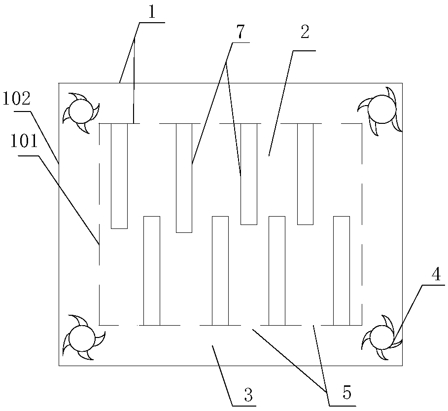
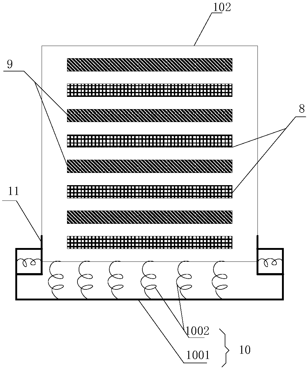
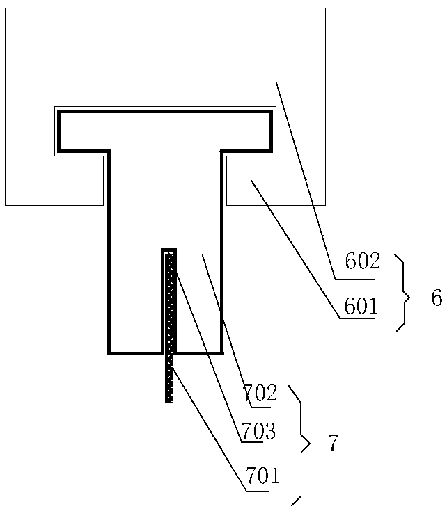
[0030] figure 1 It shows an implementation form of a novel dry-type transformer according to the present invention, which includes:

[0031] A dry-type transformer body 2 provided with an outer casing 1;

[0032] The outer casing is composed of a first casing 101 and a second casing 102, and a hollow cavity 3 is sealed between the first casing and the second casing, and the preset position of the cavity is A plurality of matching exhaust fans 4 are provided, through which the exhaust fans can accelerate the air flow circulation speed in the casing, accelerate the heat dissipati...


PUM


Abstract

The invention discloses a novel dry transformer. The novel dry transformer comprises a dry transformer body provided with an outer shell; the outer shell is composed of a first shell and a second shell, a hollow cavity is also sealed between the first shell and the second shell, the preset position of the cavity is provided with a plurality of exhaust fans which cooperate with one another, the first shell is also provided with a plurality of through holes used for gas convection, the preset position of the first shell is provided with a plurality of bases which are arranged at intervals with preset distance, each base is detachably provided with a filter net, and the bases are arranged in an S shape along the first shell; the bases are set to be inward concave structures provided with contraction parts, the preset position of the second shell is also bonded with a plurality of uniformly arranged heat absorption cotton and soundproof cotton at intervals, and the bottom of the second shell is fixed through an elastic base. The novel dry transformer has the advantages that the heat dissipation effect is good, the dust removal efficiency is high, and the replacement, disassembly and assembly of the filter net are convenient.

Description

technical field [0001] The invention relates to a transformer. More specifically, the present invention relates to a new type of dry-type transformer. Background technique [0002] Dry-type transformers are widely used in local lighting, high-rise buildings, airports, wharf CNC mechanical equipment and other places. Simply put, dry-type transformers refer to transformers whose iron core and windings are not immersed in insulating oil. The cooling method is divided into natural air cooling ( AN) and forced air cooling (AF). When naturally air-cooled, the transformer can operate continuously for a long time at the rated capacity. When forced air cooling, the output capacity of the transformer can be increased by 50%. It is suitable for intermittent overload operation, or emergency accident overload operation; due to the large increase in load loss and impedance voltage during overload, it is in a non-economic operation state, so it should not be used for long-term continuou...

Claims


Application Information

Patent Timeline
Patent Type & Authority Applications(China)
IPC IPC(8): H01F27/02H01F27/06H01F27/08H01F27/33
CPCH01F27/085H01F27/02H01F27/025H01F27/06H01F27/33
Inventor 袁红波
Owner 四川星脉电子科技有限责任公司
Learn More