
Bus conductor connector

A connector and conductor technology, which is applied in the field of busbar conductor connectors, can solve the problems of inconvenient disassembly and assembly operations, high production cost investment, and long time consumption, so as to simplify the connection process of phase line conductors, reduce the workload of installation and connection, Effect of securing contact continuity

Pending Publication Date: 2019-02-22
WETOWN ELECTRIC GRP CO LTD
View PDF0 Cites 1 Cited by
  • Summary
  • Abstract
  • Description
  • Claims
  • Application Information

AI Technical Summary

Problems solved by technology

[0002] In the power transmission and transformation equipment in the power industry, the busbar system is generally used to provide power for the electric equipment to transmit current. The busbar system is usually composed of several sections of busway products connected through a connector structure. The connector is equipped with two conductive connecting plates. The conductors of the bus duct products in the adjacent section are connected and conducted through two conductive connecting plates. After the multi-phase conductors are respectively connected and conducted through a conductive connecting plate, they need to be connected and pressed by bolts to ensure the contact and conduction Performance, large number of parts, heavy installation and connection workload, inconvenient disassembly operation, low work efficiency, long time-consuming, high production cost investment; other existing technologies can realize mutual phase conductors of adjacent section busway products The connected connector also has the defects of complex structure, large volume and bulky, high consumption of raw materials and high cost

Method used


Image

  • Bus conductor connector
  • Bus conductor connector
  • Bus conductor connector

Examples


Embodiment Construction

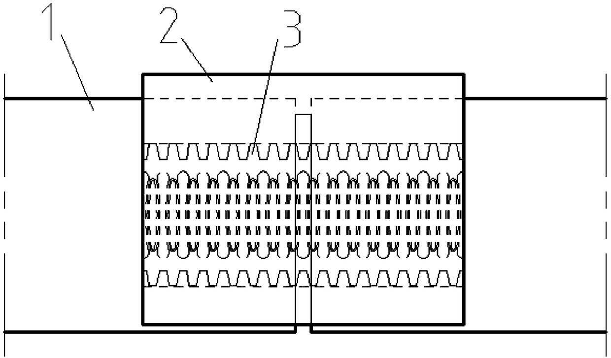
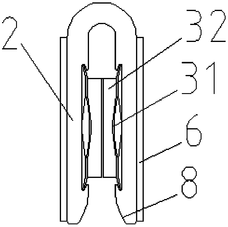
[0021] As shown in the figure, a busbar conductor connector includes two upper and lower sides, and a connecting section connected to one side of the two upper and lower sides, forming a connection with an opening on one side and a cross-sectional "U" shape. Conductor 2, horizontal "U"-shaped connecting conductor 2 The space between the upper and lower sides constitutes a socket slot 4 that can be inserted into a pair of adjacent pair of bus duct product phase line conductors 1, and the adjacent one For bus duct products, the phase line conductor 1 can be inserted into the socket slot horizontally from the opening side of the horizontal "U"-shaped connecting conductor 2 at the same time, and is connected and conducted through the horizontal "U"-shaped connecting conductor; the socket slot 4 is up and down The inner walls are respectively provided with card slots 5 extending transversely, and the sheet-shaped strip-shaped elastic conductors 3 are respectively clamped in the card...


PUM


Abstract

In a bus conductor connector of the invention, a pair of phase line conductors of adjacent segment bus duct products are transversely propelled and inserted into a plug-in slot in the horizontal direction from an opening side of a transversely-disposed "U" shaped connecting conductor and are in contact and conducted by the transversely-disposed "U" shaped connecting conductor, and the bus conductor connector is simple in structure and is convenient to operate; and a sheet strip-shaped elastic conductor snapped to a clamping slot on the upper and lower inner walls of the plug-in slot compressesthe phase line conductors of the bus duct products through a bulge part to ensure the contact conduction performance, and mark bosses or mark grooves on the upper and lower surfaces of the transversely-disposed "U" shaped connecting conductor can provide a longitudinal positioning structure for the pair of phase line conductors of adjacent segment bus duct products, and so, the number of parts issmall, a connection process of phase line conductor of the bus duct products is simplified, installation and connection workload is reduced, the consumption time is short, an operation of dismountingand installation is convenient, the work efficiency is improved, and the production investment cost is reduced.

Description

technical field [0001] The invention relates to a busbar conductor connector. Background technique [0002] In the power transmission and transformation equipment in the power industry, the busbar system is generally used to provide power for the electric equipment to transmit current. The busbar system is usually composed of several sections of busway products connected through a connector structure. The connector is equipped with two conductive connecting plates. The conductors of the bus duct products in the adjacent section are connected and conducted through two conductive connecting plates. After the multi-phase conductors are respectively connected and conducted through a conductive connecting plate, they need to be connected and pressed by bolts to ensure the contact and conduction Performance, large number of parts, heavy installation and connection workload, inconvenient disassembly operation, low work efficiency, long time-consuming, high production cost investmen...

Claims


Application Information

Patent Timeline
IPC IPC(8): H01R13/15H01R13/24H01R13/20H01R13/629
CPCH01R13/15H01R13/20H01R13/2414H01R13/2435H01R13/629
Inventor 蒋文功周忠
Owner WETOWN ELECTRIC GRP CO LTD
Learn More