Battery charging system and charging method
A battery charging and rechargeable battery technology, which is applied in the direction of secondary battery charging/discharging, charging and maintenance charging/discharging, battery circuit devices, etc., can solve the problem of high cost of charging system and other issues
- Summary
- Abstract
- Description
- Claims
- Application Information
AI Technical Summary
Problems solved by technology
Method used
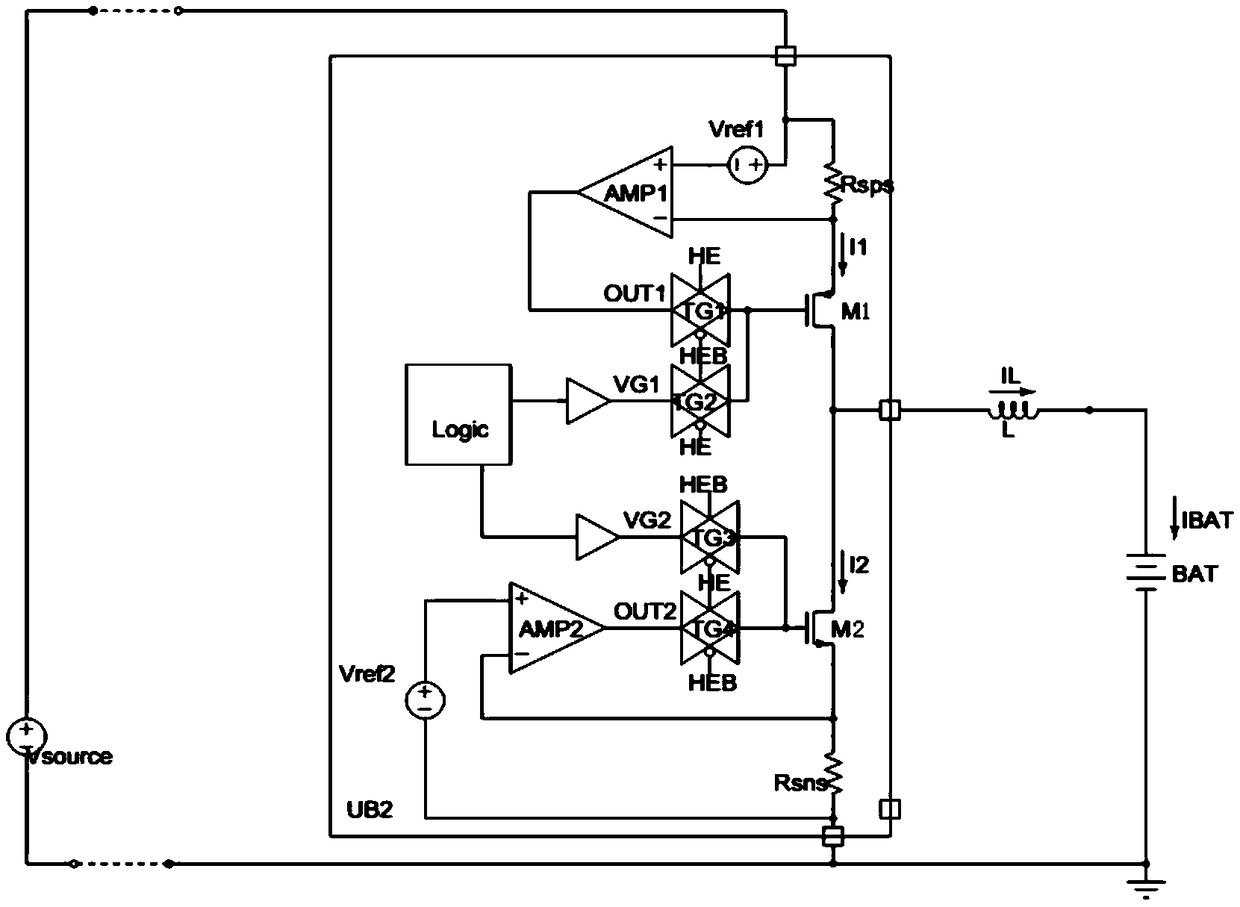
Image

Examples
Embodiment 1
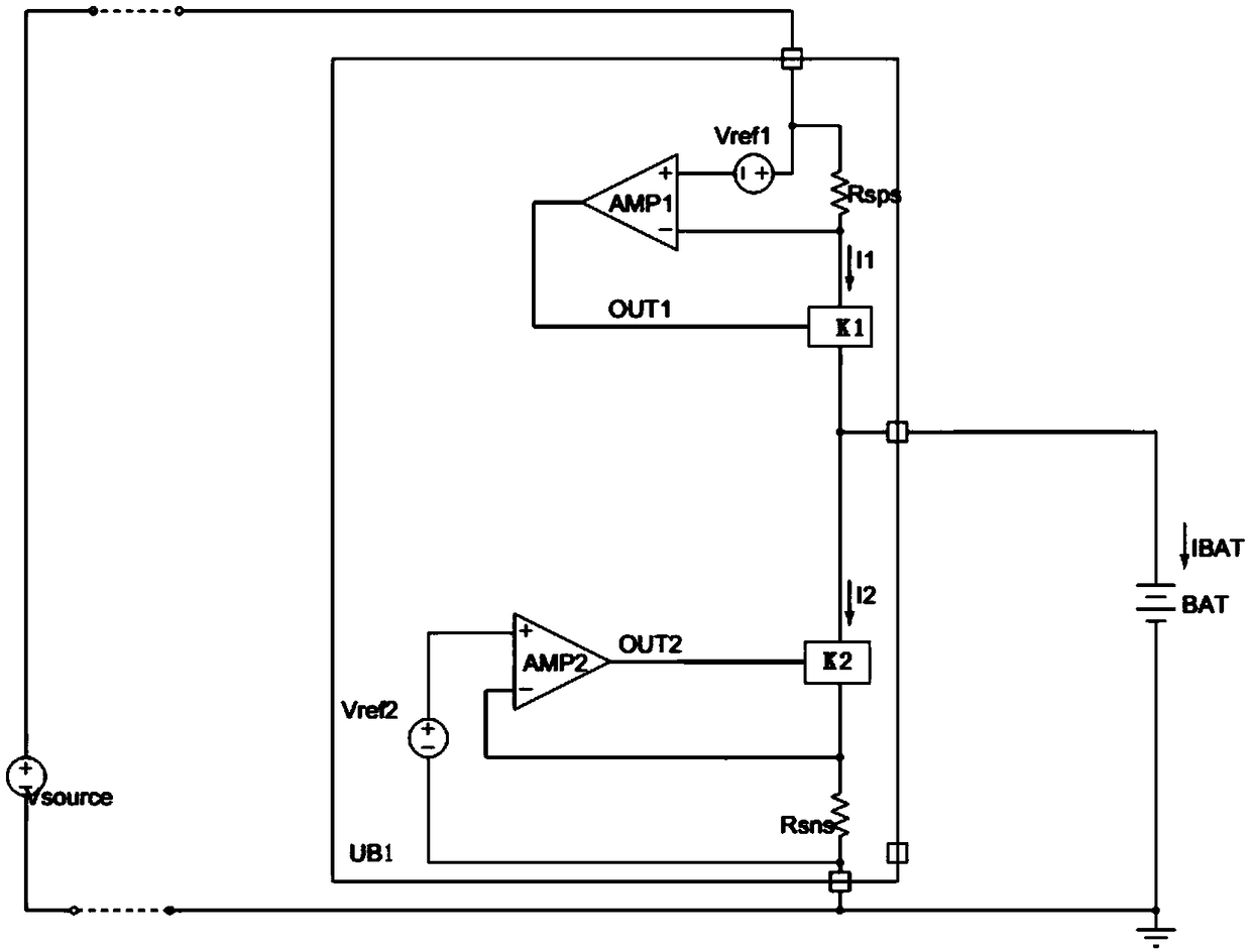
[0067] figure 1 A schematic circuit diagram of a charging system according to an embodiment of the present invention is shown.
[0068] Such as figure 1 As shown, the charging system includes: a power supply Vsource, a charging management unit and a rechargeable battery BAT, and the power supply Vsource supplies power to the charging management unit; the charging management unit includes a first control module, a second control module, a first power switch K1, and a second power switch K1. The switch tube K2; the power switch tube includes a first terminal, a second terminal, and a third terminal, and the first terminal is used to control the conduction or cut-off of the current between the second terminal and the third terminal; the output terminal OUT1 of the first control module It is connected to the first terminal of the first power switch tube K1, and the input end is connected to the second terminal of the first power switch tube K1 for controlling the first current va...
Embodiment 2
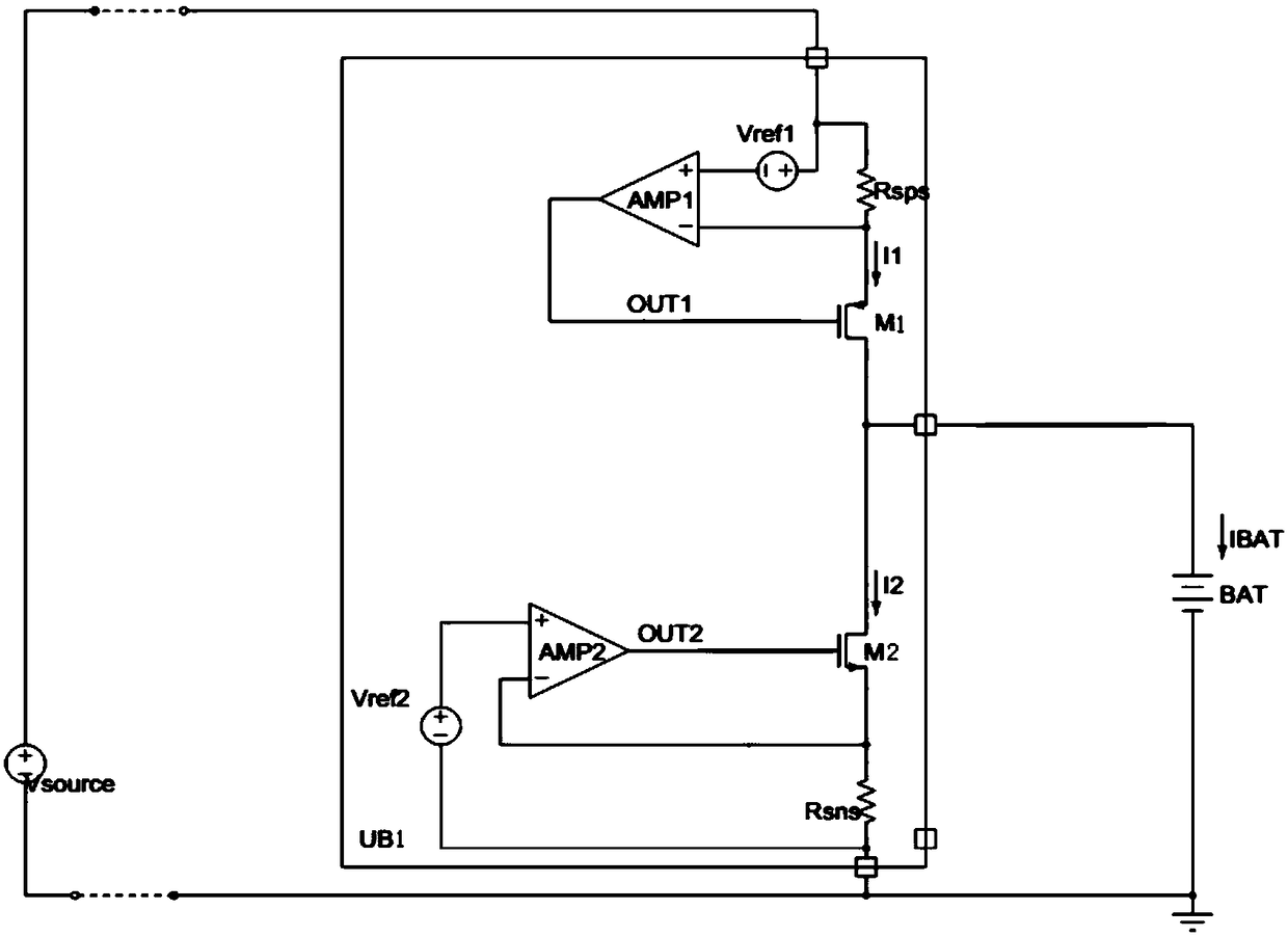
[0070] figure 2 It shows a schematic circuit diagram of a charging system applied in a charging system using a linear charging management chip of a MOS transistor according to an embodiment of the present invention.
[0071] Such as figure 2 As shown, the present invention is applied in a linear charging management chip, the first switching power tube is selected as a PMOS tube, and the second switching power tube is selected as an NMOS tube, including a power supply Vsource, a charging management unit, a rechargeable battery BAT, a first MOS tube M1, and a second switching power tube. Two MOS transistors M2; the drain of the first MOS transistor M1 is connected to the drain of the second MOS transistor M2; the positive pole of the rechargeable battery BAT is connected between the drain of the first MOS transistor M1 and the drain of the second MOS transistor M2 , the negative pole is connected to the negative pole of the power supply Vsource. One end of the first resistor...
PUM
 Abstract
Description
Claims
Application Information