Water-cooled heat dissipation structure of three-level frequency converter

A three-level frequency converter, water-cooled heat dissipation technology, applied in the transformation of equipment structural parts, electrical equipment structural parts, cooling/ventilation/heating transformation, etc., can solve problems such as high internal temperature, affecting work, and large power consumption , to achieve the effect of expanding the heat dissipation range, improving the service life and cooling effect quickly

Inactive Publication Date: 2019-02-22
山东迈易特传动有限公司
View PDF0 Cites 4 Cited by
  • Summary
  • Abstract
  • Description
  • Claims
  • Application Information

AI Technical Summary

Problems solved by technology

[0004] The purpose of the present invention is to solve the shortcomings in the prior art, such as: when the frequency converter is working, its power consumption is relatively large, and the cooling effect of the commonly used air-cooled heat dissipation on the frequency converter is not obvious, so that the inside of the frequency converter The heat cannot be dissipated in time, which will cause the internal temperature to be too high and affect the work, which will easily shorten the service life of the inverter

Method used


Image

  • Water-cooled heat dissipation structure of three-level frequency converter
  • Water-cooled heat dissipation structure of three-level frequency converter
  • Water-cooled heat dissipation structure of three-level frequency converter

Examples


Embodiment Construction

[0020] The following will clearly and completely describe the technical solutions in the embodiments of the present invention with reference to the accompanying drawings in the embodiments of the present invention. Obviously, the described embodiments are only some, not all, embodiments of the present invention.

[0021] In describing the present invention, it should be understood that the terms "upper", "lower", "front", "rear", "left", "right", "top", "bottom", "inner", " The orientation or positional relationship indicated by "outside", etc. is based on the orientation or positional relationship shown in the drawings, and is only for the convenience of describing the present invention and simplifying the description, rather than indicating or implying that the referred device or element must have a specific orientation, so as to Specific orientation configurations and operations, therefore, are not to be construed as limitations on the invention.

[0022] refer to Figure ...


PUM


Abstract

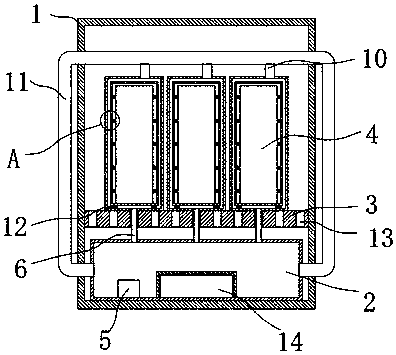
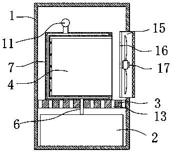
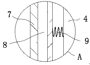
The invention discloses a water-cooled heat dissipation structure of a three-level frequency converter. The structure includes a shell. A water storage tank is fixedly connected to the bottom of the shell. A water pump is fixedly connected to the inside of the water storage tank. A separating plate is arranged on the upper end of the water storage tank. The separating plate is fixedly connected tothe inside of the shell. Three frequency converters are arranged on the upper end of the separating plate. Three tank bodies are fixedly connected to the separating plate. A water cooling cavity is arranged in the side wall of each tank body. The three frequency converters are respectively placed in the three tank bodies. Three water inlet pipes communicating with the water storage tank are arranged on the water storage tank. According to the invention, the water pump pressurizes to make water enter the water cooling cavities of the tank bodies from the water inlet pipes, heat is transferredto the cold water in the water cooling cavity through heat conducting springs, and so most of the range of the frequency converters can be cooled by water cooling. The water then enters a return pipefrom water outlet pipes and flows back from the return pipe to the water storage tank for recycling. Therefore, the water cooling range is larger, which makes the cooling effect faster and better.

Description

technical field [0001] The invention relates to the technical field of frequency converter heat dissipation, in particular to a water-cooled heat dissipation structure of a three-level frequency converter. Background technique [0002] The frequency converter is a power control device that uses frequency conversion technology and microelectronics technology to control the AC motor by changing the frequency of the motor's working power supply. The frequency converter adjusts the voltage and frequency of the output power supply by switching off the internal IGBT, and provides the required power supply voltage according to the actual needs of the motor, thereby achieving the purpose of energy saving and speed regulation. In addition, the frequency converter has many protection functions , such as overcurrent, overvoltage, overload protection, etc. With the continuous improvement of industrial automation, frequency converters have also been widely used. [0003] In order to pr...

Claims


Application Information

Patent Timeline
Patent Type & Authority Applications(China)
IPC IPC(8): H02M7/00H05K7/20
CPCH02M7/003H05K7/20909H05K7/20927
Inventor 尹超刘化立张培军黄虹连
Owner 山东迈易特传动有限公司
Why Eureka
Try Eureka