Eureka AIR delivers breakthrough ideas for toughest innovation challenges, trusted by R&D personnel around the world.

Optical signal transmission method and system for indoor wireless network

An indoor wireless and transmission method technology, applied in the transmission system, electromagnetic wave transmission system, optical fiber transmission and other directions, can solve the problem of wireless communication equipment occupying a certain time, reducing the transmission efficiency of optical signals, etc., to achieve suitable for promotion, high modulation rate , the effect of not occupying spectrum resources

Active Publication Date: 2020-10-16
WUHAN POST & TELECOMM RES INST CO LTD
View PDF10 Cites 0 Cited by
  • Summary
  • Abstract
  • Description
  • Claims
  • Application Information

AI Technical Summary

Problems solved by technology

[0003] (1) The available modulation bandwidth of wireless access technology is limited to the range of microwaves, which is different from the band of optical signals. Therefore, wireless access technology requires wireless communication equipment (such as wireless routers) to modulate the band of optical signals and then transmit them to At the same time, the start-up and work of wireless communication equipment will take a certain amount of time, which will inevitably reduce the transmission efficiency of optical signals

Method used

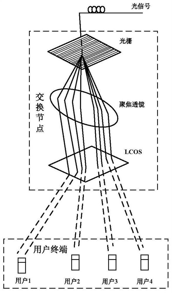

Image

  • Optical signal transmission method and system for indoor wireless network
  • Optical signal transmission method and system for indoor wireless network
  • Optical signal transmission method and system for indoor wireless network

Examples


Embodiment Construction

[0030] The present invention will be further described in detail below in conjunction with the drawings and embodiments.

[0031] The optical signal transmission method for indoor wireless network in the embodiment of the present invention includes the following steps:

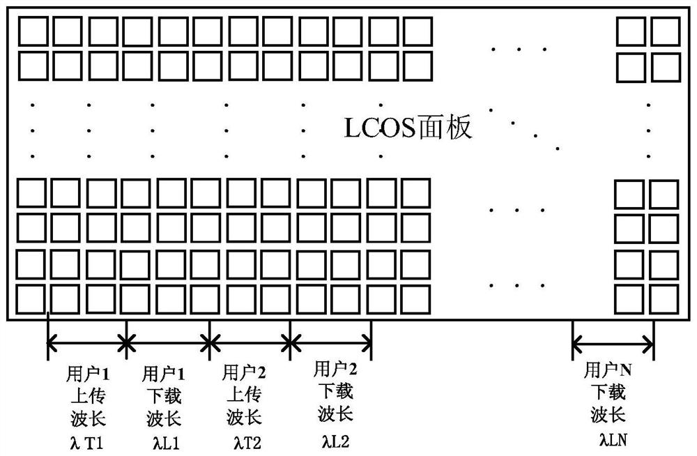
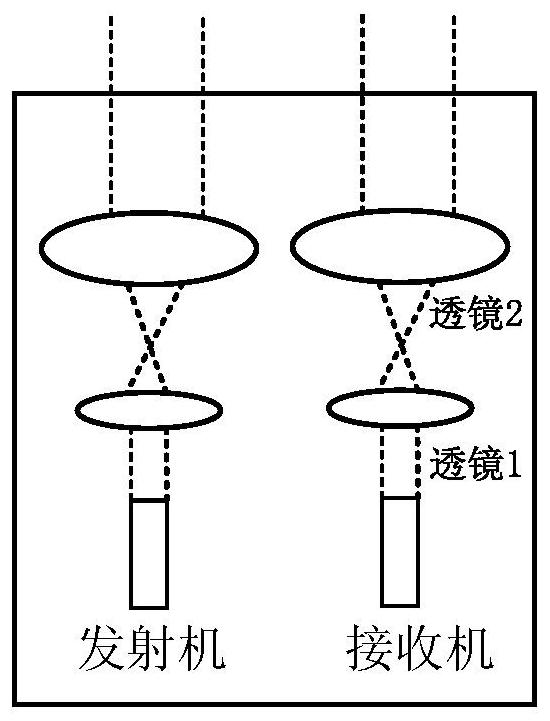
[0032] Downlink optical signal transmission process: The optical signal sending end splits the optical signal transmitted by the outside world (fiber communication system). The light of different wavelengths in the optical signal will be emitted in different directions during the splitting process; the optical signal transmitted by the outside is generally DWDM (Dense Wavelength Division Multiplexing) signal or CWDM (Coarse Wavelength Division Multiplexer, sparse wavelength division multiplexer) signal; after the split optical signal is beam-expanded, the optical signal is transmitted according to the preset download wavelength The signal is phase-modulated and sent to the user terminal.

[0033] Uplink optical sign...


PUM


Abstract

The invention discloses an optical signal transmission method and system used for an indoor wireless network, and relates to the field of optical fiber communication. The method includes following steps: a downlink optical signal transmission process: an optical signal transmitting terminal splits externally transmitted optical signals, performs beam expanding on the split optical signals, performs phase modulation on the optical signals according to a preset downloading wavelength and issues the modulated optical signals to user terminals; and an uplink optical signal transmission process: the optical signal transmitting terminal performs phase modulation on optical signals uploaded by the user terminals, focuses the optical signals after phase modulation, and couples the optical signalsto the external. According to the method and system, a wireless communication device is not adopted, direct transmission of the optical signals with non-changeable wavelength can be realized, the security performance of transmission of the optical signals is enhanced, and an optical fiber network is directly applied to the indoor wireless network.

Description

Technical field [0001] The invention relates to the field of optical fiber communication, in particular to an optical signal transmission method and system for indoor wireless networks. Background technique [0002] With the rapid growth of multimedia services in indoor wireless networks (such as home local area networks), the transmission rate of optical signals required for multimedia services is getting higher and higher. Currently, wireless access technologies (such as Wi-Fi, WiMAX, etc.) are generally used to realize the transmission of optical signals in indoor wireless networks, although wireless access technologies can meet the transmission rate of NG-PON2 (Next Generation Passive Optical Network) (10Gbps or Higher) demand, but there are the following defects in use: [0003] (1) The available modulation bandwidth of wireless access technology is limited to the microwave range, which is different from the band of optical signals. Therefore, wireless access technology requi...

Claims


Application Information

Patent Timeline
Patent Type & Authority Patents(China)
IPC IPC(8): H04B10/548H04B10/572H04B10/25
CPCH04B10/25891H04B10/548H04B10/572
Inventor 尤全刘子晨肖希
Owner WUHAN POST & TELECOMM RES INST CO LTD
Why Eureka
Eureka Blog
Learn More