Loop heat pipe

A loop heat pipe and header technology, applied in tubular elements, heat transfer modification, indirect heat exchangers, etc., can solve the problems of low heat transfer coefficient and uneven heat transfer, and achieve enhanced heat transfer and improved heat transfer effect, noise reduction effect

Inactive Publication Date: 2019-02-26
SHANDONG UNIV
View PDF4 Cites 9 Cited by
  • Summary
  • Abstract
  • Description
  • Claims
  • Application Information

AI Technical Summary

Problems solved by technology

[0007] In view of the above problems, the present invention has been improved on the basis of the previous invention, and a new heat pipe is provided, thereby solving the problems of low heat transfer coefficient and uneven heat transfer in the case of heat pipe heat exchange

Method used


Image

  • Loop heat pipe
  • Loop heat pipe
  • Loop heat pipe

Examples


Embodiment Construction

[0046] The specific embodiments of the present invention will be described in detail below in conjunction with the accompanying drawings.

[0047] In this article, if there is no special explanation, when it comes to formulas, " / " means division, and "×" and "*" mean multiplication.

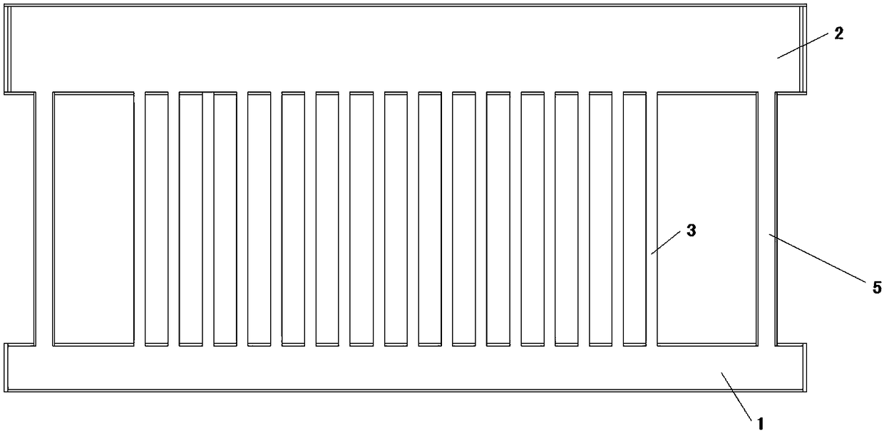
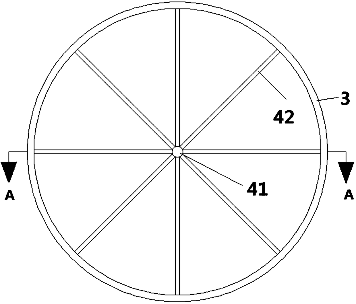
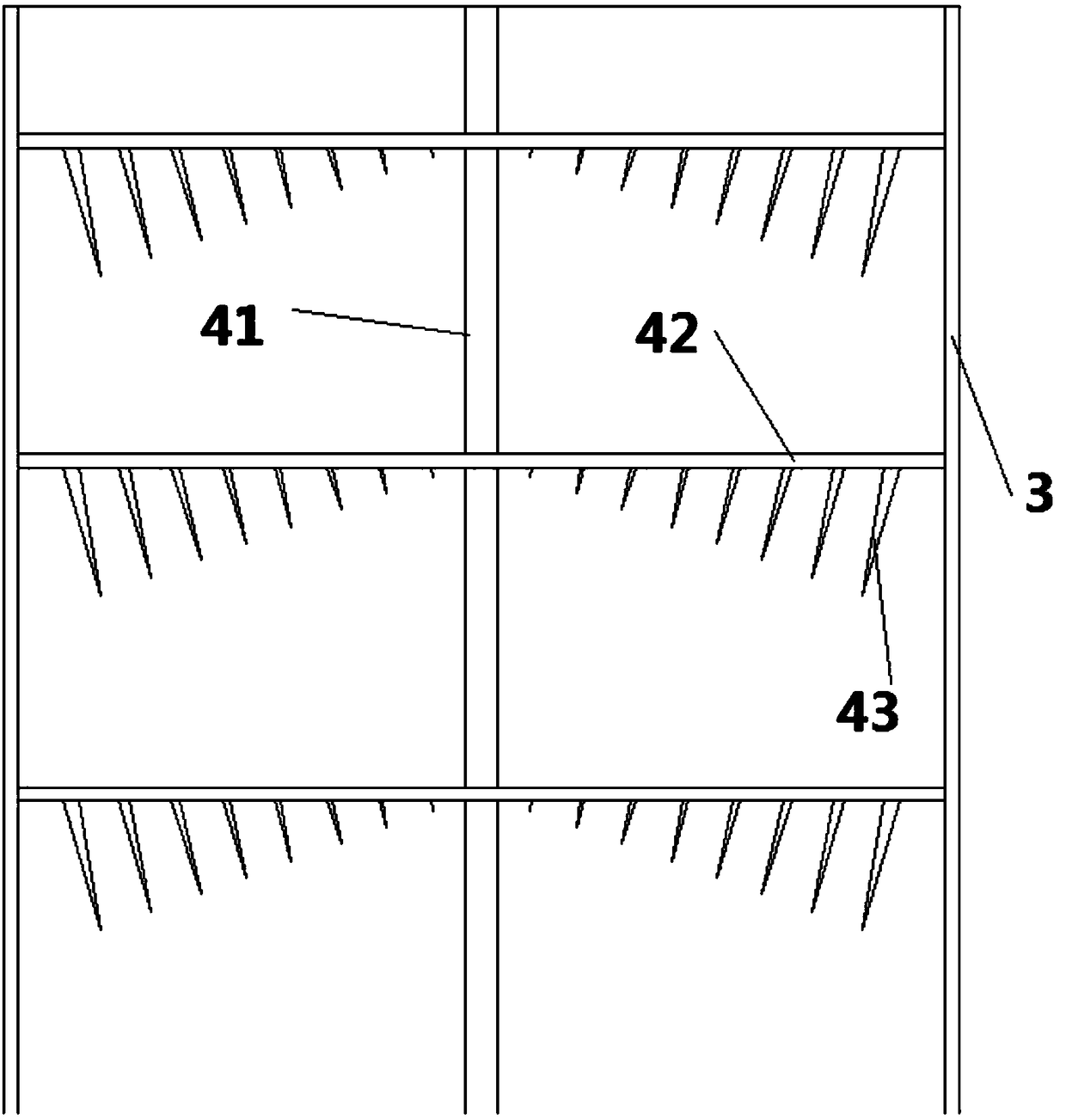
[0048] like figure 1 A heat pipe shown includes an evaporation header 1, a condensation header 2, a rising pipe 3 and a return pipe 5, the rising pipe 3 communicates with the evaporation header 1 and the condensation header 2, and the evaporation header 1 Located in the lower part, the condensation header 2 is located in the upper part, the fluid absorbs heat and evaporates in the evaporation header 1, enters the condensation header 2 through the riser 3, condenses after exchanging heat in the condensation header 2, and the condensed fluid Return to the evaporation header 1 through the return pipe 5; a flow stabilization device 4 is arranged in the riser pipe 3, and the flow stabilization device...


PUM


Abstract

The invention provides a loop heat pipe comprising an evaporation header, a condensation header, a riser tube and a return tube; the riser tube is in communication with the evaporation header and thecondensation header, the evaporation header is located at a lower portion, and the condensation header is located at an upper portion; the fluid absorbs heat in the evaporation header and evaporates,passes through the riser tube and enters the condensing header, and condenses after heat exchange in the condensing header, and the condensed fluid returns to the evaporation header through the returntube; a flow stabilization device is disposed in the riser tube, and the flow stabilization device comprises a central rod disposed along a central axis of the riser tube and a plurality of radial rods extending radially along the central rod; the radial rod is provided with a plurality of fins extending downward from the radial rod, the fins having a tip with the tip facing downward. The invention provides a loop heat pipe of a new type of flow stabilization device. By providing the radial rod and the downward tip fin, when there is a vapor-liquid two-phase flow in the riser tube, the heat transfer is enhanced, and the vibration of the riser tube is weakened, and the noise level is lowered.

Description

technical field [0001] The invention belongs to the field of heat pipes, in particular to a heat exchange heat pipe. Background technique [0002] Heat pipe technology is a heat transfer element called "heat pipe" invented by George Grover of Los Alamos National Laboratory in the United States in 1963. It makes full use of the principle of heat conduction and phase change medium. The rapid heat transfer properties of the heat pipe quickly transfer the heat of the heating object to the heat source, and its thermal conductivity exceeds that of any known metal. [0003] Heat pipe technology was widely used in aerospace, military and other industries before. Since it was introduced into the radiator manufacturing industry, people have changed the traditional radiator design ideas and got rid of the single heat dissipation mode that only relies on high air volume motors to obtain better heat dissipation. The use of heat pipe technology enables the radiator to obtain a satisfacto...

Claims


Application Information

Patent Timeline
Patent Type & Authority Applications(China)
IPC IPC(8): F28D15/02F28F1/40F28F13/06
CPCF28F1/40F28D15/0266
Inventor 郭春生曲芳仪刘海孙蛟年显勃陈子昂江程
Owner SHANDONG UNIV
Why Eureka
Try Eureka