Yunjie mill and applying method thereof and products processed with Yunjie mill

A kind of Yunjie and host technology, which is used in Yunjie mill and Yunjie grinding field for drying and grinding of high-humidity and high-viscosity materials, which can solve the problems of weakened impact, insufficient pressure difference, and temperature rise.

Inactive Publication Date: 2019-03-01
KUNMING TEKANG TECH CO LTD
View PDF0 Cites 11 Cited by
  • Summary
  • Abstract
  • Description
  • Claims
  • Application Information

AI Technical Summary

Problems solved by technology

[0003] Invention patent 2015110139212 "Completely closed-circuit circulating fluidized bed and its use and application method" discloses a device that uses a fan to crush materials and realizes rapid drying and pulverization in the process of high-speed circulation in the circulation channel, and its use and application method. In practice, it is found that this kind of equipment still cannot effectively solve the problem of material sticking to the pipe wall or hanging on the wall for most high-humidity and high-viscosity materials such as fresh agricultural products, meat, liquid materials, etc., as described in claims 5-18 Methods and products are also difficult to implement economically
[0004] Invention patent 2017111181038 discloses a mill for drying and making powder of high-humidity and high-viscosity materials and its application method. It improves the problems existing in 2015110139212. It realizes dry grinding of materials in the process of high-speed circulating flow inside the main machine The equipment named Yunjie Mill uses a Yunjie Mill host with a structure similar to that of the fan for drying and milling. Through the internal circulation pipe, the internal circulation pipe interface equivalent to the outlet of the fan is connected to the internal circulation pipe installed on the volute of the fan. The outlet interface of the tube or the outlet interface of the internal circulation tube set on the feed pipe realizes the internal circulation of the fluidized material, and the grinding blades on the rotor are used for grinding, and then the grading blades on the rotor cooperate with the discharge pipe to realize drying. Compared with the equipment described in 2015110139212, the separation of raw materials and wet materials has made significant progress, and the effect of processing materials with low moisture content is not bad, but there are still the following defects. The impact of the volute corresponding to the blade will cause a large amount of wet material to adhere here. 2. The classification effect is not good, and a small part of the wet material will be discharged from the shell cover into the discharge pipe and adhere to it. 3. Equipment The pressure difference between the inlet and outlet depends on the difference between the outlet diameter of the middle cover and the inlet diameter of the front cover. A large increase makes it difficult to achieve normal temperature operation. In addition, the internal resistance of the main engine makes the material circulation flow too high and the energy consumption is too high, resulting in poor economy.

Method used


Image

  • Yunjie mill and applying method thereof and products processed with Yunjie mill
  • Yunjie mill and applying method thereof and products processed with Yunjie mill
  • Yunjie mill and applying method thereof and products processed with Yunjie mill

Examples


Embodiment 1

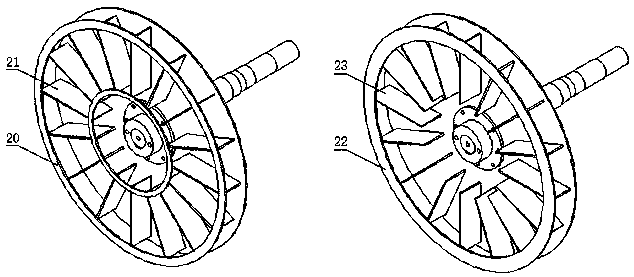
[0120] Embodiment 1: the first kind of impeller of main engine of Yunjie mill, see attached figure 2 , the impeller shown in the left figure adopts the method of opening an annular window on the front disc 20 to expose the blades 21 to realize the airflow from the inner circulation pipe interface can push the impeller to rotate by impacting the exposed blades; figure 2 The impeller shown in the middle right figure adopts the method of enlarging the inlet on the front disc 22 so that the blades 23 are exposed to realize that the airflow from the inner circulation pipe interface can push the impeller to rotate by impacting the exposed blades.

Embodiment 2

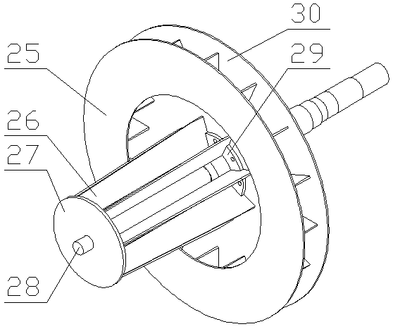
[0121] Embodiment 2: the second kind of impeller of the main engine of the Yunjie mill, see the attached image 3 , the power vane 26 of the main engine impeller of the second kind of Yunjie mill is arranged in the inlet of the front disc 25, one end is fixed on the shaft sleeve 29 and the rear disc 30, and the other end stretches into the feed pipe to be connected with the connecting plate 27, and the connecting plate 27 Fixed on the shaft 28 extending along the inlet, the air flow from the inner circulation pipe interface can push the impeller to rotate by impacting the power blade 26 . The power blade 26 of the second kind of Yun clean mill main frame also can be fixed on the axle sleeve 29 in an end in the front disc 25, or on the rear disc 30.

Embodiment 3

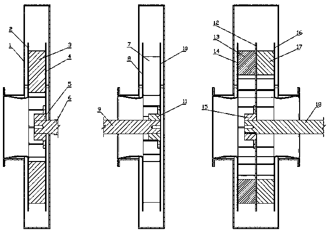
[0122] Embodiment 3: the first kind of Yunjie mill host, see attached Figure 4 , improved on the basis of a centrifugal fan, consisting of a casing 31 and an impeller 32, the casing 31 has an internal circulation pipe interface 33 near the entrance, and the impeller adopts the two first types of impellers of the main engine of the Yunjie mill described in Embodiment 1 One, the airflow from the internal circulation pipe interface 33 can push the impeller to rotate by impinging on the blades.


PUM


Abstract

The invention discloses a Yunjie mill. The technical scheme that powder milling and drying are finished in a Yunjie mill set in the high-speed circulating flowing process of materials is adopted to realize rapid drying and powder manufacturing in a normal temperature of high-humidity and high-viscosity materials such as fresh agricultural products, and the deficiency existing in equipment of a patent for an invention 2017111181038 is overcome. According to an applying method of the Yunjie mill, the common pain point problems that the quality is poor or the cost is high when a traditional method is used for processing fresh plant materials, meat, liquid materials and the like are solved, an economical solving scheme is provided for processing of feeding agricultural products, and preparation of medicine with volatile components as functional components and the like. According to the products processed by the Yunjie mill, links which generates quality problems in the processing process of the traditional method are eliminated, the finishing time of drying and powder manufacturing is shortened to be within three minutes, and special flavors of the materials under the fresh condition of the products are preserved.

Description

technical field [0001] The invention relates to a rhizome clean mill used for dry grinding, in particular to a rhizome clean grinder used for dry grinding of high-humidity and high-viscosity materials, belonging to the technical field of circulating fluidized bed, the technical field of Chinese herbal medicine processing, and agricultural products Processing technology field, drying and grinding technology field. Background technique [0002] Centrifugal fan is a kind of gas conveying equipment, see attached figure 1 , usually consists of two parts: the casing 1 and the impeller. For the forward air fan, the impeller is composed of the front disk 2, the blade 3, the rear disk 4 on the side of the input shaft 6, and the shaft sleeve 5. For the rear air fan, the impeller is composed of The front disc 10, the blades 7, the rear disc 8 on the side of the input shaft 9, and the shaft sleeve 11 are composed. The rear plate 16 on one side and the shaft sleeve 15 are composed. For...

Claims


Application Information

Patent Timeline
Patent Type & Authority Applications(China)
IPC IPC(8): B02C13/02B02C13/26B02C23/20F26B3/084F26B21/02F26B25/22
CPCF26B3/084F26B21/02F26B25/22B02C13/02B02C13/26B02C23/20B02C13/08B02C13/282B02C13/288B02C21/00B02C23/28B02C23/18B02C23/14Y02B10/50Y02P60/85Y02P70/10
Inventor 贾平曾亚文杨韵洁杨军贾芸菁
Owner KUNMING TEKANG TECH CO LTD
Why Eureka
Try Eureka