
Intelligent welding method, system and device and storage medium

A welding method and intelligent technology, applied in auxiliary devices, welding equipment, program-controlled manipulators, etc., can solve problems such as difficult machine adjustment, affecting product quality and service life, and long time-consuming, so as to improve work efficiency and product quality , Reduce the workload of manual debugging and achieve a high degree of automation

Active Publication Date: 2019-03-01
WUHAN XINYUAN TUOER TECH CO LTD
View PDF6 Cites 11 Cited by
  • Summary
  • Abstract
  • Description
  • Claims
  • Application Information

AI Technical Summary

Problems solved by technology

[0003] 1. Determine the amount of tin given according to the size of the pad; the amount of tin given will consume different heat energy, so the time to return to the set temperature after melting tin will be different, so the welding time must be adjusted, often on one board There will be pads of different sizes, which brings great difficulties to debugging
[0004] 2. The thickness of the pcb board is different, and the heat dissipation will be different after the solder pen touches the board. If the temperature of the pad is not enough during soldering, there will be a virtual soldering, which will affect the quality and service life of the product.
[0005] 3. All solder joints will change in temperature due to environmental conditions, such as wind, temperature changes and the initial temperature of the soldering pen, after the soldering time is adjusted and the amount of tin is given. The result of the temperature change will make the soldering spot welding or overheating
[0006] 4. From the above, it can be seen that the automatic soldering machine has extremely high requirements for the adjustment personnel, and the adjustment is difficult and time-consuming. If the amount of products produced is not very large, it basically does not make much sense

Method used


Image

  • Intelligent welding method, system and device and storage medium
  • Intelligent welding method, system and device and storage medium

Examples


Embodiment Construction

[0053] The principles and features of the present invention are described below in conjunction with the accompanying drawings, and the examples given are only used to explain the present invention, and are not intended to limit the scope of the present invention.

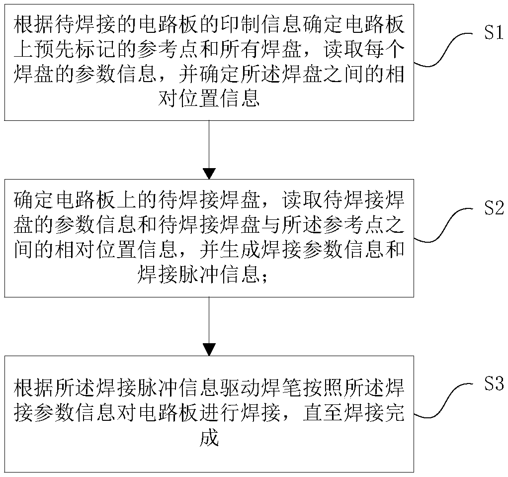
[0054] Such as figure 1 Shown, a kind of intelligent welding method comprises the following steps:

[0055] Step 1: Determine the pre-marked reference points and all pads on the circuit board according to the printed information of the circuit board to be soldered, read the parameter information of each pad, and determine the relative position information between the pads;

[0056] Step 2: Determine the pad to be welded on the circuit board, read the parameter information of the pad to be soldered and the relative position information between the pad to be soldered and the reference point, and generate welding parameter information and welding pulse information;

[0057] Step 3: Drive the soldering pen according to...


PUM


Abstract

The invention relates to an intelligent welding method, system and device and a storage medium. The method comprises the steps of determining pre-marked reference points and all welding discs on a circuit board according to printing information of the circuit board to be welded, reading parameter information of each welding disc and determining relative position information between the welding discs; determining the welding discs to be welded on the circuit board, reading parameter information of the welding discs to be welded and the information about the relative positions between the welding discs to be welded and the reference points, generating welding parameter information and welding pulse information, and according to the welding parameter information and the welding pulse information, welding the circuit board; the parameter information of the welding discs to be welded on the circuit board and the information about the relative positions between the welding discs to be weldedand the reference points are obtained, the welding parameter information and the welding pulse information are generated, the circuit board is precisely welded, different soldering tin amounts are applied according to different welding discs, the manual debugging workloads at the early period are greatly reduced, work efficiency and product quality are improved, and the automation degree is high.

Description

technical field [0001] The invention relates to the technical field of welding automation, in particular to an intelligent welding method, system, device and storage medium. Background technique [0002] In the field of electronics industry, especially after wave soldering, reflow soldering and placement machine of electronic products, electric soldering iron is required for part of the solder joints. In the case of rising labor costs, automatic soldering equipment has begun to appear on the market. The current Automatic welding equipment is mainly multi-dimensional platform automatic soldering machine. The advantage of the multi-dimensional platform soldering machine is that it can greatly reduce labor, and the welding quality is more stable and reliable than manual welding. It is suitable for mass production and the cost is relatively low. However, the early debugging is particularly critical, and the debugging time is long. The requirements are also quite high. Its main...

Claims


Application Information

Patent Timeline
IPC IPC(8): B23K1/00B23K3/00B23K3/08B25J11/00B25J9/16
CPCB23K1/0008B23K3/00B23K3/08B25J9/161B25J9/1697B25J11/005
Inventor 张弛李建成谢红明范文吉彭奥黄烈海
Owner WUHAN XINYUAN TUOER TECH CO LTD
Learn More