RH vacuum system regulating vacuum device and application

A vacuum system and vacuum device technology, applied in the field of iron and steel smelting, can solve the problems of increasing the vacuuming time and the like

Pending Publication Date: 2019-03-01
MCC CAPITAL ENGINEERING & RESEARCH
View PDF5 Cites 3 Cited by
  • Summary
  • Abstract
  • Description
  • Claims
  • Application Information

AI Technical Summary

Problems solved by technology

Normally, after each furnace is processed, it is necessary to close the vacuum main valve first, so as to perform vacuum breaking operations on the vacuum tank side and the vacuum pump side respectively, and then open the...

Method used


Image

  • RH vacuum system regulating vacuum device and application

Examples


Embodiment 1

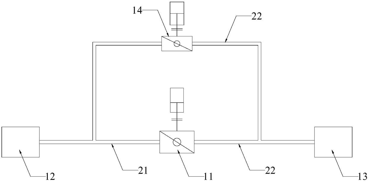
[0024] see figure 1 , A RH vacuum system regulating vacuum device provided by an embodiment of the present invention includes: a vacuum main valve 11 , a first pipeline 21 , a second pipeline 22 , a bypass pipeline 22 and a bypass valve 14 . One end of the first pipeline 21 is connected to the main vacuum valve 11 , and the other end is connected to the vacuum tank 12 of the RH vacuum refining device; one end of the second pipeline 22 is connected to the main vacuum valve, and the other end is connected to the vacuum pump 13 .

[0025] Wherein the bypass valve 14 is installed on the bypass pipeline 22, the diameter of the valve is about DN300mm, and the diameter of the valve is determined according to the pressure difference on both sides and the time required to balance the pressure. The inner diameter ratio of the bypass pipeline 23 and the first pipeline 21 is 1:5.

[0026] In the embodiment, after each furnace is processed, first close the vacuum main valve 11, open the v...


PUM


Abstract

The invention provides an RH vacuum system regulating vacuum device and application. The device includes a vacuum main valve (11), a first pipeline (21), a second pipeline (22), a bypass pipeline (23)and a bypass valve (14), wherein one end of the vacuum main valve (11) is provided with the first pipeline (21) for connection with an RH vacuum refining device, the other end is provided with the second pipeline (22) for connection with a vacuum pump; the first pipeline (21) and the second pipeline (22) are connected through the bypass pipeline (23), and the bypass valve (14) is disposed on thebypass pipeline (23) and forms a parallel connection relationship with the vacuum main valve (11). By vacuuming a vacuum pump side system after RH vacuum treatment, the bypass valve is adopted to balance the vacuum pressure on both sides of the vacuum main valve, the vacuum pump system can be quickly started, the vacuum system emptying time can be shortened, and the consumption of a medium like steam can be saved, and the effect of the RH processing cycle is shortened.

Description

technical field [0001] The invention relates to the field of iron and steel smelting, in particular, the invention relates to an RH vacuum system regulating vacuum device and its application. Background technique [0002] The RH method, that is, the vacuum cycle degassing method, was jointly developed by the former Ruhrstahl and Heraeus in 1957, so it became the RH method. Vacuum treatment is an important step in refining outside the furnace. The method plays a very important role in providing steel product quality, expanding quality, reducing costs, and optimizing steelmaking production processes. It is currently an indispensable production equipment for steel types such as automotive sheets, electrical steel, and pipeline steel. [0003] When the RH method is used to treat molten steel, the ladle is first sent to the processing position with a ladle car, and the ladle is lifted to make the dipping tube dip a certain distance below the liquid steel surface, and then start t...

Claims


Application Information

Patent Timeline
IPC IPC(8): C21C7/10
CPCC21C7/10
Inventor 杜善国李博张红兵杜俊峰王英群郑涛于灏严月祥丛芳
Owner MCC CAPITAL ENGINEERING & RESEARCH
Why Eureka
Try Eureka