Liquid chromatography combined organic carbon detector and using method thereof
A liquid chromatography and detector technology, applied in the field of water quality analysis and detection, can solve the problems of low time resolution, high difficulty in production and processing, and large volume, and achieve the effects of high time resolution, increased analysis time, and small volume
- Summary
- Abstract
- Description
- Claims
- Application Information
AI Technical Summary
Problems solved by technology
Method used
Image
Examples
Embodiment 1
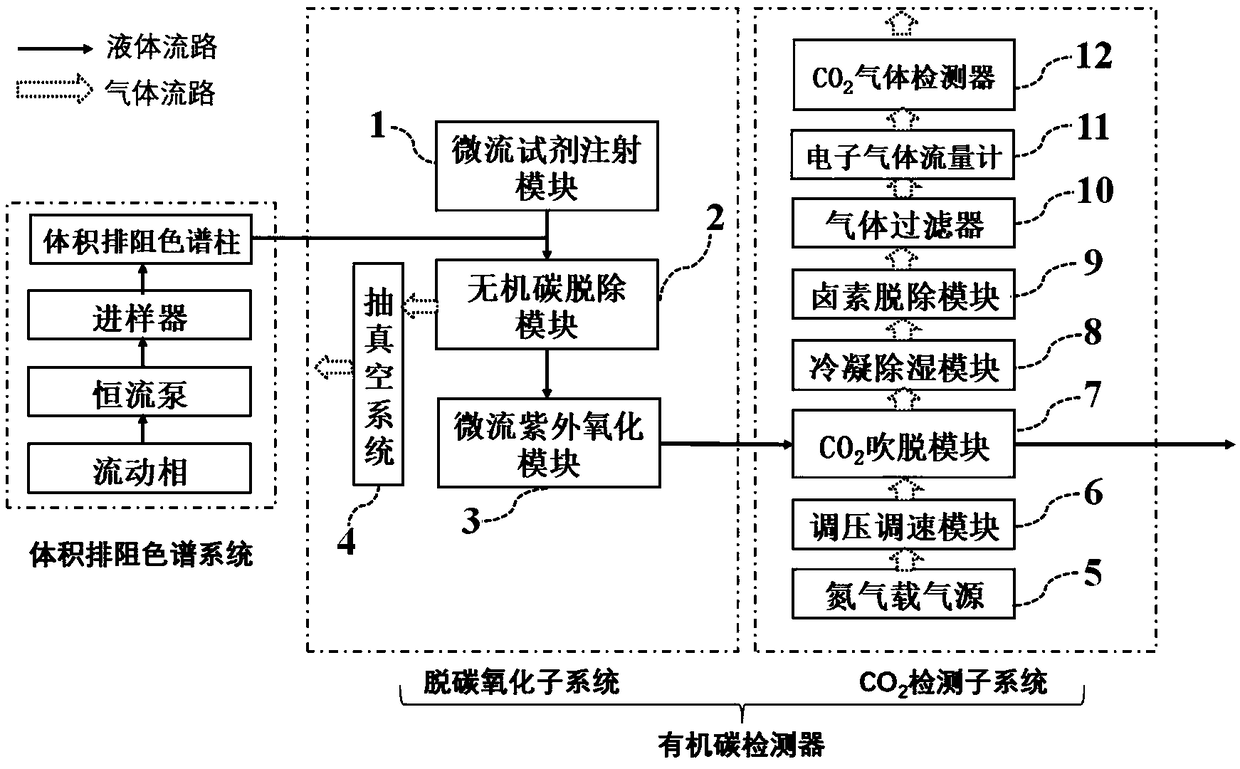
[0052] This embodiment provides a liquid chromatography coupled organic carbon detector, such as figure 1 As shown, it includes microfluidic reagent injection module 1, inorganic carbon removal module 2, microfluidic ultraviolet oxidation module 3, vacuum system 4, nitrogen carrier gas source 5, pressure and speed regulation module 6, CO 2 Stripping module 7, stripping gas treatment components and CO 2 The gas detector 12 ; the stripping gas processing component further includes a condensation dehumidification module 8 , a halogen removal module 9 , a gas filter 10 and an electronic gas flow meter module 11 .
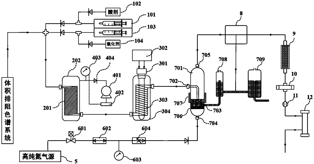
[0053] Such as figure 2 As shown, the microfluidic reagent injection module 1 includes an acidic agent microfluidic injection pump 101, an acidic agent storage box 102 and a microfluidic pipeline; the acidic agent microfluidic injection pump drives a screw rod through a precision stepping motor to pull a microinjector After extracting the acid agent from the acid age...
Embodiment 2
[0067] This embodiment is basically the same as Embodiment 1, the difference is:
[0068] Such as Figure 4 As shown, the microfluidic reagent injection module 1 only uses the acidic agent microfluidic injection pump 101, the acidic agent storage box 102 and the microfluidic pipeline, and does not use the function of injecting oxidizing agent into the mobile phase, and its oxidation function mainly depends on ultraviolet light. Radiation is irradiated into the microfluidic pipeline 303 to generate strong oxidizing hydroxyl radicals to achieve this.
[0069] Such as Figure 4 As shown, the inorganic carbon removal module 2 adopts a PTFE capillary tube with an inner diameter of 0.25mm and an outer diameter of 1.20mm, and the line length is 10m.
[0070] Such as Figure 4As shown, the microfluidic pipeline 303 in the microfluidic ultraviolet oxidation module 3 adopts a microfluidic quartz chip, the purity of the quartz material used is JGS1 level, the width of the microfluidic...
Embodiment 3
[0073] This embodiment is basically the same as Embodiment 1, the difference is:
[0074] Such as Figure 6 As shown, the microfluidic pipeline 303 in the microfluidic ultraviolet oxidation module 3 adopts a microfluidic quartz chip, the purity of the quartz material used is JGS1 level, the width of the microfluidic groove in the chip is 0.40mm, and the height is 0.20mm , the S-shaped arrangement is densely distributed in the quartz chip, the effective area is 8cm long, 4cm wide, and the total length of the flow path is about 4m; the ultraviolet lamp 301 is suspended and placed under the microfluidic pipeline 303 (ie, the microfluidic quartz chip), with a distance of 2mm ;
[0075] Such as Figure 6 As shown, the nitrogen carrier gas source 5 provides high-purity nitrogen as the carrier gas. After being processed by the pressure regulation and speed regulation module 6, nitrogen at a certain flow rate first passes through the housing 304 of the microflow ultraviolet oxidatio...
PUM
| Property | Measurement | Unit |
|---|---|---|
| length | aaaaa | aaaaa |
Abstract
Description
Claims
Application Information
 - R&D
- Intellectual Property
- Life Sciences
- Materials
- Tech Scout
- Unparalleled Data Quality
- Higher Quality Content
- 60% Fewer Hallucinations
Browse by: Latest US Patents, China's latest patents, Technical Efficacy Thesaurus, Application Domain, Technology Topic, Popular Technical Reports.
© 2025 PatSnap. All rights reserved.Legal|Privacy policy|Modern Slavery Act Transparency Statement|Sitemap|About US| Contact US: help@patsnap.com


