
A signal test fixture, system and test method

A signal testing and jig technology, applied in the testing field, can solve the problems of inaccurate test results and affect the test results, and achieve the effect of facilitating signal testing, improving accuracy, and eliminating the impact.

Active Publication Date: 2020-10-30
INSPUR SUZHOU INTELLIGENT TECH CO LTD
View PDF10 Cites 0 Cited by
  • Summary
  • Abstract
  • Description
  • Claims
  • Application Information

AI Technical Summary

Problems solved by technology

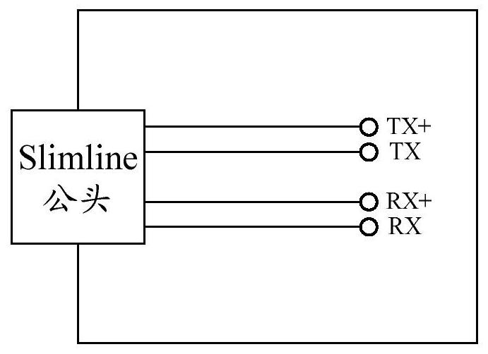
[0003] The current test fixture used for SATA signal testing of the Slimline interface generally leads the SATA signal directly through the PCB (Printed Circuit Board, printed circuit board). Although the test can be realized in this way, an additional PCB is introduced into the test fixture. Routing, the PCB routing on the test fixture will affect the test results during the test, resulting in inaccurate test results

Method used


Image

  • A signal test fixture, system and test method
  • A signal test fixture, system and test method
  • A signal test fixture, system and test method

Examples


Embodiment Construction

[0038] The application describes a number of embodiments, but the description is illustrative rather than restrictive, and it will be obvious to those of ordinary skill in the art that within the scope of the embodiments described in the application, There are many more embodiments and implementations. Although many possible combinations of features are shown in the drawings and discussed in the detailed description, many other combinations of the disclosed features are possible. Except where expressly limited, any feature or element of any embodiment may be used in combination with, or substituted for, any other feature or element of any other embodiment.

[0039] This application includes and contemplates combinations of features and elements known to those of ordinary skill in the art. The disclosed embodiments, features and elements of this application can also be combined with any conventional features or elements to form unique inventive solutions as defined by the clai...


PUM


Abstract

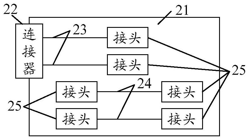
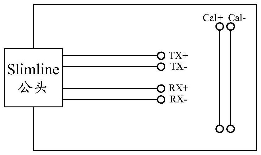
The invention provides a signal test fixture, a system, and a test method. The signal test fixture includes: a printed circuit board; and a connector for leading a to-be-tested signal of a to-be-tested interface to the printed circuit. The printed circuit board is provided with a transmission differential line and a calibration differential line. One end of the transmission differential line is connected to the connector, and the other end is provided with a connector, and the transmission differential line is used to transmit a to-be-tested signal of the to-be-tested interface to the connector. Two ends of the calibration differential line are respectively provided with a joint for collecting scattering parameters of the calibration differential line. The scattering parameters of the calibration difference line and the transmission differential line are the same. The signal test fixture can improve accuracy of test results when performing signal tests.

Description

technical field [0001] This article relates to testing technology, especially to a signal testing fixture, system and testing method. Background technique [0002] With the continuous improvement of board density, the packaging size of components is getting smaller and smaller, and Slimline (thin wire cable) is used more and more widely as a high-density, small-size connector. The signal pins of the Slimline interface have a high density and are all wrapped, and the SATA (Serial Advanced Technology Attachment, Serial Advanced Technology Attachment) signal of the Slimline interface is a high-speed signal, and the SATA signal needs to be tested for signal integrity. [0003] The current test fixture used for SATA signal testing of the Slimline interface generally leads the SATA signal directly through the PCB (Printed Circuit Board, printed circuit board). Although the test can be realized in this way, an additional PCB is introduced into the test fixture. Routing, the PCB ro...

Claims


Application Information

Patent Timeline
Patent Type & Authority Patents(China)
IPC IPC(8): G01R1/04G01R31/00
CPCG01R1/0416G01R31/00
Inventor 贾永涛
Owner INSPUR SUZHOU INTELLIGENT TECH CO LTD
Learn More