

Signal source of S-band wave radar
A wave-measuring radar and signal source technology, applied in the field of microwave Doppler radar, can solve problems such as not using miniaturization, compact design, increasing system volume, affecting radar system performance, etc., to achieve miniaturization, signal-to-noise The effect of high ratio and low signal phase noise
- Summary
- Abstract
- Description
- Claims
- Application Information
AI Technical Summary
Problems solved by technology
Method used
Image

Examples
Embodiment Construction
[0036] The present invention will be further described below in conjunction with drawings and embodiments.
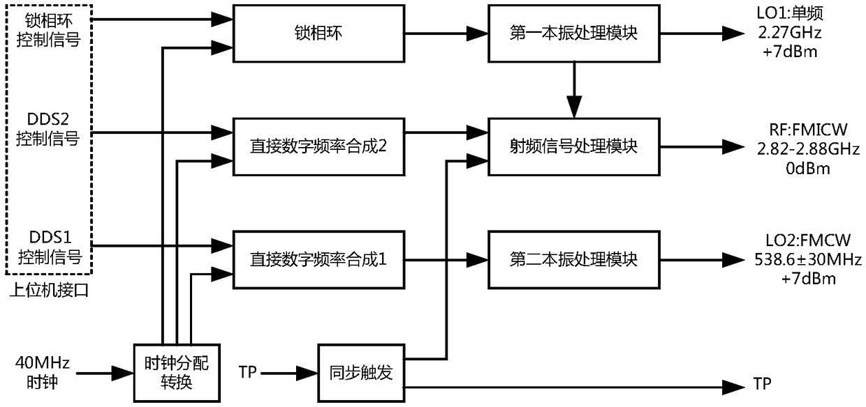
[0037] figure 1 A block diagram of a signal source circuit of an S-band wave-measuring radar provided by an embodiment of the present invention. as attached figure 1 As shown, the signal source of an S-band wave-measuring radar described in the embodiment of the present invention includes clock distribution conversion, synchronous triggering, direct digital frequency synthesis 1, direct digital frequency synthesis 2 integrated on a printed circuit board , a phase-locked loop, a first local oscillator processing module, a radio frequency signal processing module and a second local oscillator processing module. The signal waveform generation of this scheme is based on the direct digital frequency synthesis technology (DDS), and by improving the traditional signal generation circuit and the composition form of the radio frequency processing circuit, etc., it provides two...
PUM
 Abstract
Description
Claims
Application Information