Beating device for surface light source and beating method thereof

A technology of a printing device and a surface light source, applied in the field of backlight sources, can solve the problems of high cost, low mass production efficiency, and long transfer time of the surface light source, etc.

Active Publication Date: 2019-03-01
BOE TECH GRP CO LTD +1
View PDF5 Cites 2 Cited by
  • Summary
  • Abstract
  • Description
  • Claims
  • Application Information

AI Technical Summary

Problems solved by technology

[0003] Embodiments of the present invention provide a surface light source printing device and a printing method thereof, which can solve the problems of high cost and low mass production efficiency of the existing surface light source due to too long transfer time

Method used


Image

  • Beating device for surface light source and beating method thereof
  • Beating device for surface light source and beating method thereof
  • Beating device for surface light source and beating method thereof

Examples


Embodiment Construction

[0023] The following will clearly and completely describe the technical solutions in the embodiments of the present invention with reference to the accompanying drawings in the embodiments of the present invention. Obviously, the described embodiments are only some, not all, embodiments of the present invention. Based on the embodiments of the present invention, all other embodiments obtained by persons of ordinary skill in the art without making creative efforts belong to the protection scope of the present invention.

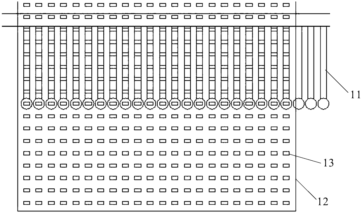
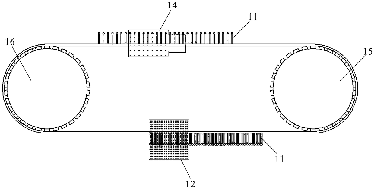
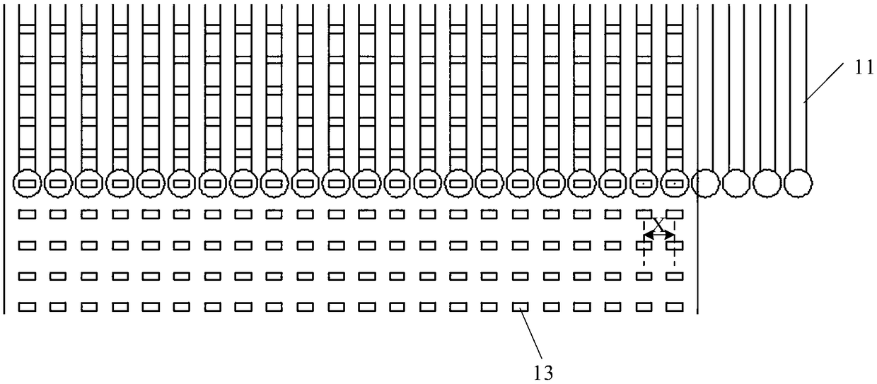
[0024] An embodiment of the present invention provides a surface light source punching device, such as Figure 1 to Figure 5 As shown, it includes: a grabbing mechanism, the grabbing mechanism includes at least one grabbing group, each grabbing group includes a plurality of grabbing arms 11, and the plurality of grabbing arms 11 in the same grabbing group are used to extract from the expansion plate 12 grabs a plurality of LED wafers 13 at the same time, and t...


PUM


Abstract

The embodiment of the invention provides a beating device for a surface light source and a beating method thereof, and relates to the technical field of a backlight source. The problem that the surface light source has high cost and low mass production efficiency due to excessive transfer time is solved. The beating device comprises a gripping mechanism, the gripping mechanism comprises at least one gripping group, each gripping group comprises a plurality of gripping arms, and a plurality of the gripping arms in the same gripping group are used for simultaneously grasping a plurality of LED wafers from a crystal expansion plate and transferring a plurality of the LED wafers to a flexible circuit board; a stroke amplifying mechanism is used for amplifying spacing between the plurality of gripping arms of the LED wafers to make spacing between the adjacent two gripping arms match the spacing between positions to place the adjacent LED wafers on the flexible circuit board; a stroke reduction mechanism is used for reducing the spacing between the plurality of gripping arms which release the LED wafers, so that the spacing between the adjacent two gripping arms matches the spacing between the adjacent LED wafers in the plurality of LED wafers to be captured on the crystal expansion plate. The device is used for making the surface light source.

Description

technical field [0001] The invention relates to the technical field of backlight sources, in particular to a surface light source mounting device and a mounting method thereof. Background technique [0002] In recent years, due to the wider color gamut of Mini LED (Light Emitting Diode, light-emitting diode), which can bring advantages such as higher brightness, longer service life and higher contrast ratio, it has been favored in the field of backlight for liquid crystal displays. a high degree of attention. However, because the existing Mini LED die-bonding methods are all single-shot crystals, and the die-bonding is carried out by positioning with a robot arm. This leads to too long transfer time of Mini LED, which in turn leads to higher cost of Mini LED and lower mass production efficiency. Contents of the invention [0003] Embodiments of the present invention provide a surface light source printing device and a printing method thereof, which can solve the problems...

Claims


Application Information

Patent Timeline
Patent Type & Authority Applications(China)
IPC IPC(8): G02F1/13G02F1/13357
CPCG02F1/1303G02F1/133603
Inventor 芮博超王雪绒陈雷汪志强马鑫孙川王秋里
Owner BOE TECH GRP CO LTD
Why Eureka
Try Eureka