Railway power equipment history management system and method based on fault location function

A fault location, power equipment technology, applied in data processing applications, geographic information databases, database design/maintenance, etc., can solve problems such as large number of required, power outage running production, operation, difficult to accurately locate, etc., to reduce labor strength, eliminate power accidents, and reduce the effect of manual intervention

Inactive Publication Date: 2019-03-01
中铁一院(陕西)工程建设有限公司 +2
View PDF6 Cites 4 Cited by
  • Summary
  • Abstract
  • Description
  • Claims
  • Application Information

AI Technical Summary

Problems solved by technology

Railway power overhead lines are long and span many regions. Especially in the northwest of China, they often pass through uninhabited areas, deserts, Gobi and other sparsely populated areas. In this environment, a single power supply line fails, and it is difficult to find it in time. Even if it is found, it is very difficult Difficult to accurately locate and carry out inspection and maintenance, often causing serious problems such as power outages, running production, and operation
[0003] Fault location of existing power overhead lines is not easy to install, poor positioning accuracy, high cost, etc. If you want to locate each pole, you need to install a detection device on each pole. If this is implemented on the entire railway line, the required quantity is huge. The cost is extremely high, and the later equipment installation, maintenance and maintenance will also increase a lot of unnecessary workload

Method used


Image

  • Railway power equipment history management system and method based on fault location function
  • Railway power equipment history management system and method based on fault location function
  • Railway power equipment history management system and method based on fault location function

Examples


Embodiment Construction

[0032] The present invention will be described in detail below in combination with specific embodiments.

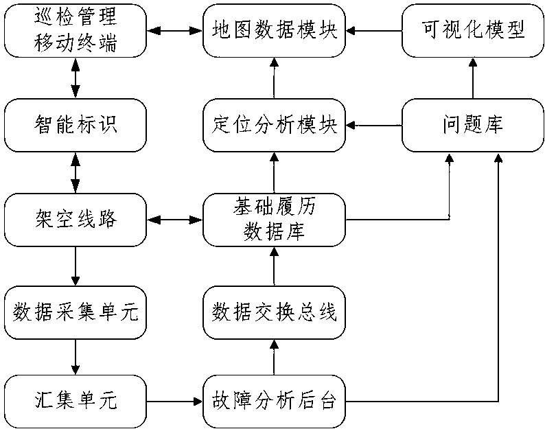
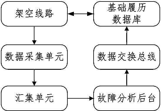
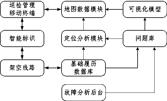
[0033] The history management system of railway power equipment based on the fault location function involved in the present invention includes an overhead line, a data acquisition unit, a collection unit, a fault analysis background, a data exchange bus, a basic history database, a question bank, a visualization model, a map data module, a tour Inspection and management of mobile terminals and smart signs;

[0034] The overhead line is connected to the data acquisition unit, and the data collected by the data acquisition unit is transmitted to the fault analysis background through the collection unit, and the fault analysis background is connected to the basic history database through the data exchange bus, and the data in the basic history database corresponds to the overhead line data;

[0035] The basic history database and the fault analysis background collect proble...


PUM


Abstract

The invention relates to a railway electric power equipment history management system based on fault location function and a method thereof. The system monitors an overhead line on-line through a dataacquisition unit, analyzes a real-time fault, returns to a foundation history database for storage through a data exchange bus, and corresponds to the actual data of the field overhead line one by one. Combined with the fault data to form the problem library, combined with the overhead line visual model, pushed to the patrol management mobile terminal, the terminal to the overhead line intelligent identification data association; the overhead line collects the fault information through the data acquisition unit, transmits the fault analysis background analysis by the aggregation unit, and then imports the results into the basic resume database. Combined with the data results of the positioning analysis module, the map positioning and navigation guidance are carried out through the map data module, and the site fault point is uniquely confirmed. The implementation of the invention can improve the accuracy of the intelligent judgment, reduce the manual patrol workload, and realize the ring-type data flow and fault comprehensive analysis and positioning of the overhead line facilities with the whole life cycle closed.

Description

technical field [0001] The invention relates to a power fault location system, in particular to a railway power equipment history management system and method based on the fault location function. Background technique [0002] Railway power overhead lines are an important part of the power system. The railway system grows into a large belt. The power overhead lines erected along the railway are not only large in number and variety, but also directly related to the stability and safety of power transmission, directly affecting the railway. normal operation. Railway power overhead lines are long and span many regions. Especially in the northwest of China, they often pass through uninhabited areas, deserts, Gobi and other sparsely populated areas. In this environment, a single power supply line fails, and it is difficult to find it in time. Even if it is found, it is very difficult It is difficult to accurately locate and carry out inspection and maintenance, often causing ser...

Claims


Application Information

Patent Timeline
Patent Type & Authority Applications(China)
IPC IPC(8): G06F16/21G06F16/26G06F16/29G06Q50/06
CPCG06Q50/06
Inventor 李晋赵乐李宁林林彭明宣田世骥牛金平宫衍圣王颢刘贻军
Owner 中铁一院(陕西)工程建设有限公司
Why Eureka
Try Eureka