Check patentability & draft patents in minutes with Patsnap Eureka AI!

Revolving speed observation method for induction machine

An induction motor and rotational speed technology, applied in the field of induction motor rotational speed observation, can solve problems such as low identification accuracy

Inactive Publication Date: 2019-03-01
天津恒天新能源汽车研究院有限公司
View PDF3 Cites 0 Cited by
  • Summary
  • Abstract
  • Description
  • Claims
  • Application Information

AI Technical Summary

Problems solved by technology

[0004] Based on this, it is necessary to provide an induction motor speed observation method for the low identification accuracy of the traditional induction motor speed identification method.

Method used


Image

  • Revolving speed observation method for induction machine
  • Revolving speed observation method for induction machine
  • Revolving speed observation method for induction machine

Examples


Embodiment approach

[0102] Further, in step S100, the stator current vector i of the induction motor in the stationary αβ coordinate system s Component i on the α axis sα , the stator current vector i s Component i on the β axis sβ The collection of can be realized through the following implementation methods:

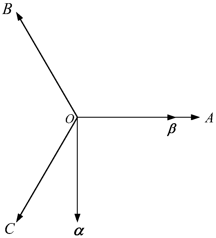
[0103] First, sample the real-time induction motor stator A-phase current i A , Stator B-phase current i B , Stator phase C current i C . Then, use the coordinate transformation of formula (9) to obtain the stator current vector i of the induction motor in the stationary αβ coordinate system s Component i on the α axis sα , the stator current vector i s Component i on the β axis sβ .

[0104]

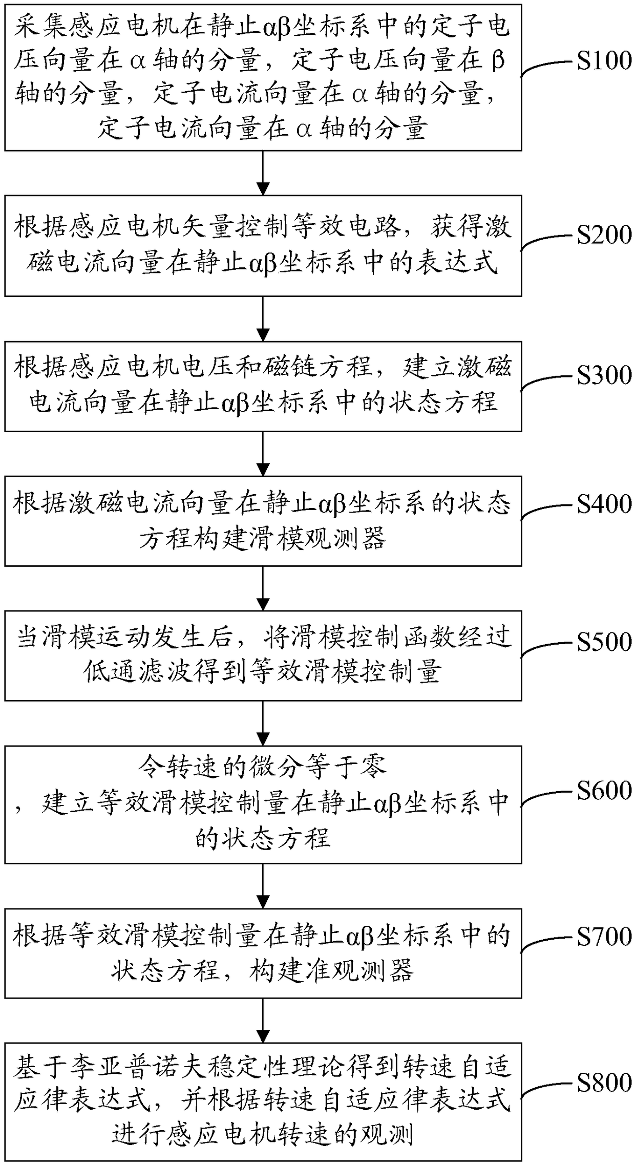
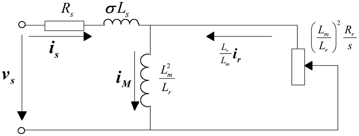
[0105] see figure 1 and image 3 , when step S100 is completed, step S200 can be performed to control the equivalent circuit according to the vector of the induction motor to obtain the excitation current vector i M The expression in the stationary αβ coordinate system:

[0106] ...


PUM


Abstract

The invention discloses a revolving speed observation method for an induction machine. The method comprises the following steps that: collecting the components of the stator voltage vector of the induction motor on an [Alpha] axis and a [Beta] axis in a static [Alpha] [Beta] coordinate system as well as the components of the stator voltage vector on the [Alpha] axis and the [Beta] axis; accordingto an induction motor vector control equivalent circuit, obtaining the expression of an excitation current vector in the static [Alpha] [Beta] coordinate system, and establishing the state equation ofthe excitation current vector in the static [Alpha] [Beta] coordinate system; according to the excitation current vector, constructing a slip form observer; after slip form motion happens, carrying out low-pass filtering on a slip form control function to obtain an equivalent slip form control quantity, and establishing the state equation of the equivalent slip form control quantity in the static[Alpha] [Beta] coordinate system; according to the state equation of the equivalent slip form control quantity, in the static [Alpha] [Beta] coordinate system, constructing a quasi observer; and on the basis of the Lyapunov stability theory, obtaining a revolving speed self-adaption expression. By use of the method, the problem of low distinguishing accuracy of a traditional induction motor revolving speed distinguishing implementation method is effectively solved.

Description

technical field [0001] The invention relates to the technical field of motor drive control, in particular to a method for observing the rotational speed of an induction motor. Background technique [0002] In the field of modern motor control, induction motor vector control technology has been widely used. The use of speed sensors destroys the advantages of induction motors such as simple structure, reliability, low cost, and convenient maintenance. At the same time, it also limits the application range of induction motors and reduces System robustness, therefore, no speed sensor has not only become an important research direction of modern AC drive control technology, but also a key technology for researching high-performance general-purpose inverters. [0003] At present, there are many implementation methods for induction motor speed identification through speed sensorless control, such as: Luenberger observer method, model reference adaptive method, neural network and sl...

Claims


Application Information

Patent Timeline
Patent Type & Authority Applications(China)
IPC IPC(8): H02P21/24H02P21/18H02P21/13H02P21/00
CPCH02P21/0007H02P21/13H02P21/18H02P21/24
Inventor 李曦
Owner 天津恒天新能源汽车研究院有限公司
Features
  • R&D
  • Intellectual Property
  • Life Sciences
  • Materials
  • Tech Scout
  • Unparalleled Data Quality
  • Higher Quality Content
  • 60% Fewer Hallucinations
Learn More