
Laser module

A laser and circuit module technology, applied in the field of electronics, can solve the problems of low circuit efficiency and large size of the laser module, and achieve the effect of satisfying laser noise compliance and avoiding electromagnetic interference.

Pending Publication Date: 2019-03-01
深圳市大族锐波传感科技有限公司
View PDF0 Cites 1 Cited by
  • Summary
  • Abstract
  • Description
  • Claims
  • Application Information

AI Technical Summary

Problems solved by technology

[0004] The laser module provided by the present invention aims to solve the problems in the prior art that the laser module is bulky and the circuit efficiency is low due to the problem of dealing with electromagnetic interference

Method used


Image

  • Laser module
  • Laser module
  • Laser module

Examples


Embodiment 1

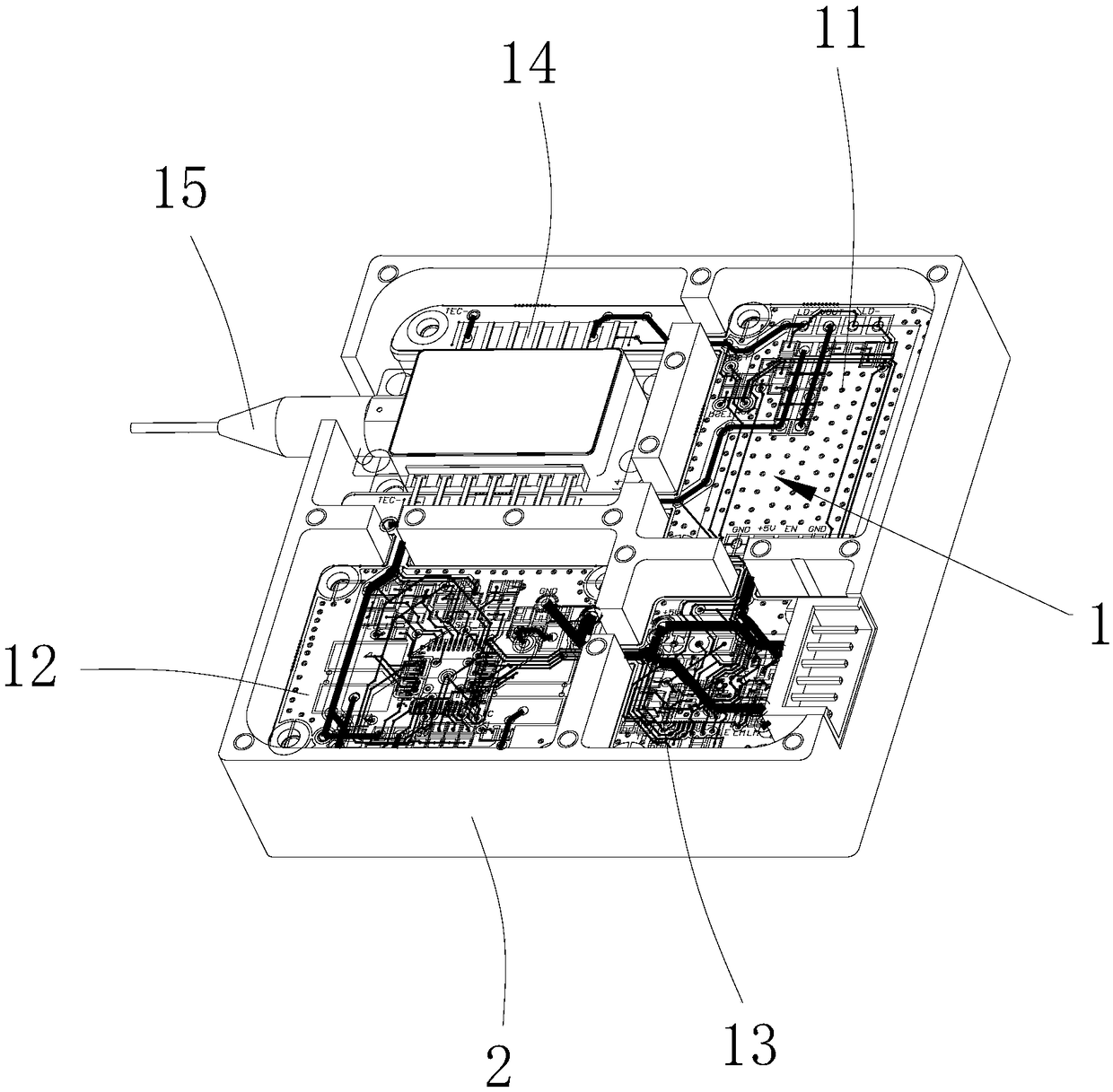
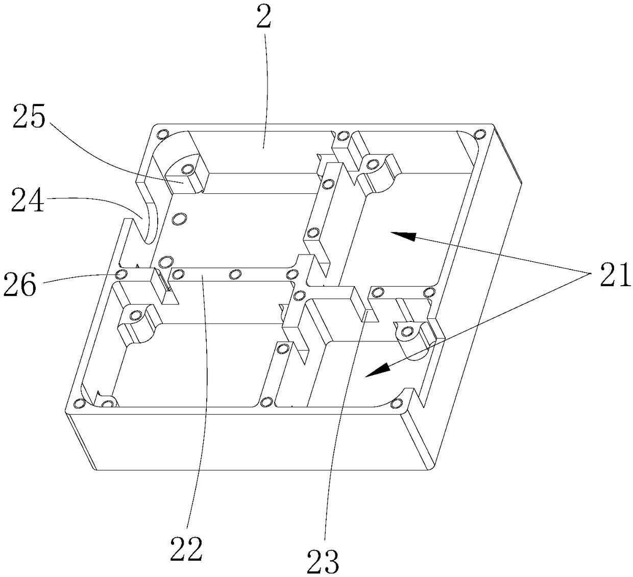
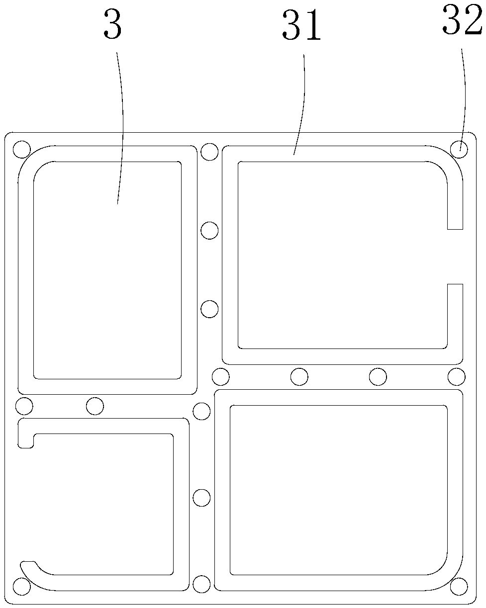
[0026] A laser module, comprising a circuit board 1, a box body 2 for preventing electromagnetic interference and a cover 3 for preventing electromagnetic interference, the cover 3 is set on the box body 2, the circuit board 1 includes a plurality of circuit modules, and the box body 2 is formed with a plurality of installation grooves 21 for placing circuit modules, and each installation groove 21 is set corresponding to each circuit module one by one, and the cover 3 is formed with a protrusion structure 31 for sealing each installation groove 21 .

[0027] In the embodiment of the present invention, each circuit module is enclosed in each installation groove 21 of the box body 2 to avoid electromagnetic interference to other areas, thereby ensuring that the output laser noise of the product meets the standard while meeting the miniaturization requirements of the equipment.

Embodiment 2

[0029] This embodiment is an improvement based on Embodiment 1. The circuit board 1 includes a laser driver module 11, a temperature adjustment module 12, a single-chip microcomputer control module 13 and a laser adapter module 14 that are electrically connected in sequence. There are four mounting slots 21 . The laser driving module 11 mainly completes the current driving function of the laser light-emitting part, which is an ultra-low noise circuit part, and is easily interfered by other parts; the temperature adjustment module 12 mainly completes the temperature adjustment of the laser light-emitting part, so that the light-emitting part emits laser light of a specific wavelength, This part is the larger part of the power, and the power of this part fluctuates greatly under different ambient temperatures, and this part is also the part that produces the larger radiation energy simultaneously; the single-chip microcomputer control module 13 mainly completes the laser module l...

Embodiment 3

[0031] This embodiment is an improvement based on Embodiment 1. Side walls 22 are formed between every two adjacent installation grooves 21, and a notch 23 is formed on each side wall 22, and the notch 23 communicates with each adjacent two installation grooves. Slot 21. The gap 23 is used for the wires between two adjacent circuit modules to pass through.


PUM


Abstract

The invention is suitable to be used in the technical field of electronics, and provides a laser module. The laser module comprises a circuit board, a box for preventing electromagnetic interference and a cover for preventing electromagnetic interference. The cover is disposed on a box body, and the circuit board comprises a plurality of circuit modules. A plurality of mounting slots for placing the circuit modules are formed on the box body, and the mounting slots are disposed in one-to-one correspondence with the circuit modules. The cover has a protruding structure for sealing each mountingslots. In the embodiment, through sealing each circuit module in each mounting slot of the box body, electromagnetic interference on other parts is prevented, thereby satisfying miniaturization requirements of equipment while ensuring output laser noise of a product to reach the standard.

Description

technical field [0001] The invention is applicable to the field of electronic technology, and in particular relates to a laser module. Background technique [0002] Due to the requirements of integration, the overall size of the laser is small, the size of the circuit board in the small volume is limited, and the distance between the components on the circuit board is too small, which will cause some signal interference in different circuit areas, such as the electromagnetic radiation of the power part. The weak signal line of the control part received interference, which caused the output laser noise of the product to fail to meet the standard. [0003] In the current technical situation, the layout of the circuit board is generally made relatively large to attenuate the electromagnetic radiation to a sufficiently small level at a sufficiently far distance. Such a design results in a large overall volume of the laser module; another way is to generate The part of electroma...

Claims


Application Information

Patent Timeline
Patent Type & Authority Applications(China)
IPC IPC(8): H05K9/00H01S5/022H01S5/042
CPCH01S5/022H01S5/042H05K9/0032H05K9/0081H05K9/0084
Inventor 毛鹤白富军云志强周卫甜黄建业娄志农
Owner 深圳市大族锐波传感科技有限公司
Learn More