A radio network node, a wireless device and methods therein for reference signal configuration

A technology of wireless equipment and network nodes, applied in the direction of pilot signal allocation, transmission path sub-channel allocation, electrical components, etc.

Inactive Publication Date: 2019-03-01
TELEFON AB LM ERICSSON (PUBL)
View PDF4 Cites 0 Cited by
  • Summary
  • Abstract
  • Description
  • Claims
  • Application Information

AI Technical Summary

Problems solved by technology

However, two or more DMRSs located in the same OFDM symbol but placed on different frequency locations (e.g., on different subcarriers) only enable time error estimation

Method used


Image

  • A radio network node, a wireless device and methods therein for reference signal configuration
  • A radio network node, a wireless device and methods therein for reference signal configuration
  • A radio network node, a wireless device and methods therein for reference signal configuration

Examples


Embodiment 1

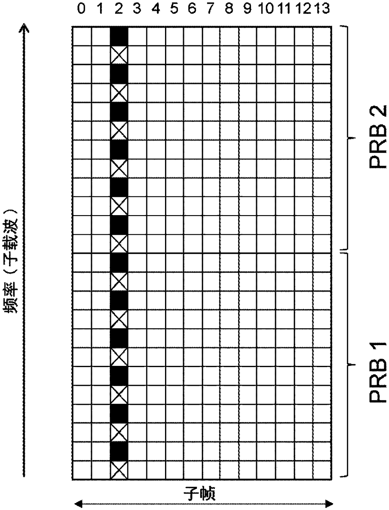
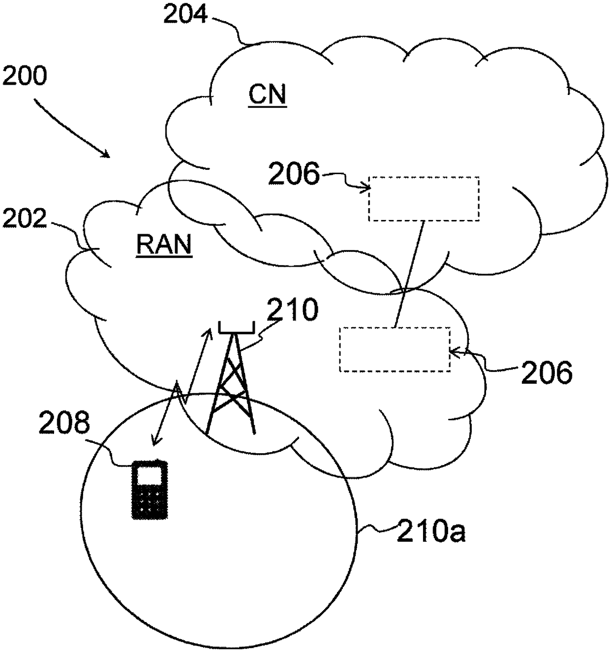
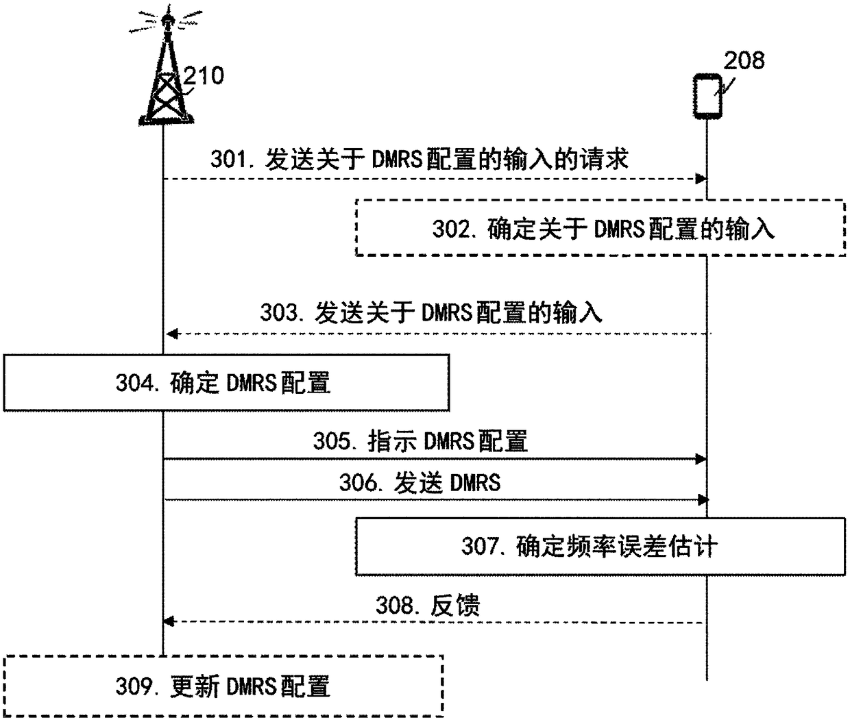
[0211] Embodiment 1. A method for configuring a demodulation reference signal DMRS of a wireless device (208) performed by a radio network node RNN (210), wherein the RNN (210) and the wireless device (208) are in a wireless Operates in a communication network (200), and wherein the method comprises:

[0212] - indicating (305, 404) to the wireless device (208) a DMRS configuration dynamically configurable to relate to one or more of:

[0213] a first Orthogonal Frequency Division Multiplexing OFDM symbol comprising a DMRS for the first transmission; and

[0214] A second OFDM symbol comprising a DMRS for the first transmission.

Embodiment 2

[0215] Embodiment 2. The method of embodiment 1, wherein the first and second OFDM symbols are included in a single subframe.

Embodiment 3

[0216] Embodiment 3. The method of embodiment 2, wherein the first OFDM symbol is located at the beginning of the subframe and the second OFDM symbol is located at the end of the subframe.


PUM


Abstract

A Radio Network Node (RNN) 210 and a method therein for configuration of Demodulation Reference Signals (DMRSs) of a wireless device 208. The RNN 210 and the wireless device 208 are operating in a wireless communications network 200. The RNN indicates a DMRS configuration to the wireless device, which DMRS configuration is dynamically configurable to relate to one or more out of a first OrthogonalFrequency- Division Multiplexing (OFDM) symbol comprising DMRSs for a first transmission; and a second OFDM symbol comprising DMRSs for the first transmission.

Description

technical field [0001] Embodiments herein relate generally to a radio network node (RNN), a wireless device and methods therein. In particular, embodiments relate to reference signal (RS) configurations, in particular high speed demodulation reference signal (DMRS) configurations. Background technique [0002] A communication device such as a terminal is also referred to as eg user equipment (UE), mobile terminal, station (STA), wireless device, wireless terminal and / or mobile station. A communication device is capable of communicating wirelessly in a wireless communication system such as a wireless local area network (WLAN) or a cellular communication network (also sometimes referred to as a cellular radio system or cellular network). Communication may be performed eg between two communication devices, between a communication device and a conventional telephone and / or between a communication device and a server, eg via an access network and possibly one or more core networ...

Claims


Application Information

Patent Timeline
IPC IPC(8): H04L5/00
CPCH04L5/0051H04L5/0091H04L5/0007H04L27/2605H04L27/2662H04L27/2666
Inventor 霍坎·安德森马蒂亚斯·弗芮妮约翰·福鲁斯克张强尼古拉斯·韦伯格
Owner TELEFON AB LM ERICSSON (PUBL)
Why Eureka
Try Eureka