
Horizontal double-layer tube rotary superconducting waste pyrolysis gasifier

A pyrolysis gasification, double-layer tube technology, applied in incinerators, lighting and heating equipment, combustion methods, etc., can solve the problem that the waste cannot reach the pyrolysis gasification temperature, cannot maintain the temperature and pressure of the reaction zone, and affects the waste pyrolysis. Gasification efficiency and other issues, to achieve the effect of reducing the generation of dioxin precursors, avoiding bonding, and strong thermal conductivity

Inactive Publication Date: 2019-03-05
西安美润环保工程技术有限公司 +1
View PDF0 Cites 5 Cited by
  • Summary
  • Abstract
  • Description
  • Claims
  • Application Information

AI Technical Summary

Problems solved by technology

[0005] At present, in the process of garbage disposal in my country, vertical furnaces are used to incinerate "gasification" garbage. The garbage is basically incinerated in the combustion furnace, and a large amount of smoke, particulate matter, acid gas, unburned waste, heavy metals and Trace organic compounds, etc., followed by a large amount of carcinogenic dioxins and heavy metals, low gas output, large ash residue, follow-up treatment is required, continuous operation is not possible, high operating costs and fixed investment
There are also traditional cracking furnaces used to treat garbage, and the garbage does not need to be incinerated. However, the existing traditional garbage cracking furnaces have a single-layer wall, and heat is supplied from the outside of the furnace wall. There is no temperature balance device in the garbage reaction zone, and the reaction zone cannot be kept relatively stable. The high temperature and pressure make it difficult for the cracking furnace to continuously and stably produce combustible gas, but still cannot avoid the generation of smoke, and cannot shield the harmful molecules released by the cracking products from polluting the environment
In particular, the traditional pyrolysis furnace body is a single-tube single-layer structure, the heater is located near the inlet end of the cracking furnace waste, and the burner is used to locally heat the single-tube single-layer body near the inlet end outside the furnace body, and the radiant heat passes through the single-layer furnace body. The body conducts to the garbage near the inlet end. Because the garbage cracking body has a large diameter and long axial direction, the single-tube single-layer body is locally heated by a thousand-degree flame, and its temperature field is uneven along the axial and radial directions of the furnace body. As a result, the heating temperature of the garbage in the furnace is uneven, resulting in local overheating and side reactions of garbage cracking, and even accidents of garbage carbonization and coking in the furnace due to local overheating
In addition, the temperature of the garbage in the furnace is always falling when it travels from the inlet end to the outlet end. Most of the garbage cannot reach the temperature conditions for cracking and gasification, which seriously affects the efficiency of garbage cracking and gasification.

Method used


Image

  • Horizontal double-layer tube rotary superconducting waste pyrolysis gasifier

Examples


Embodiment Construction

[0021] specific implementation plan

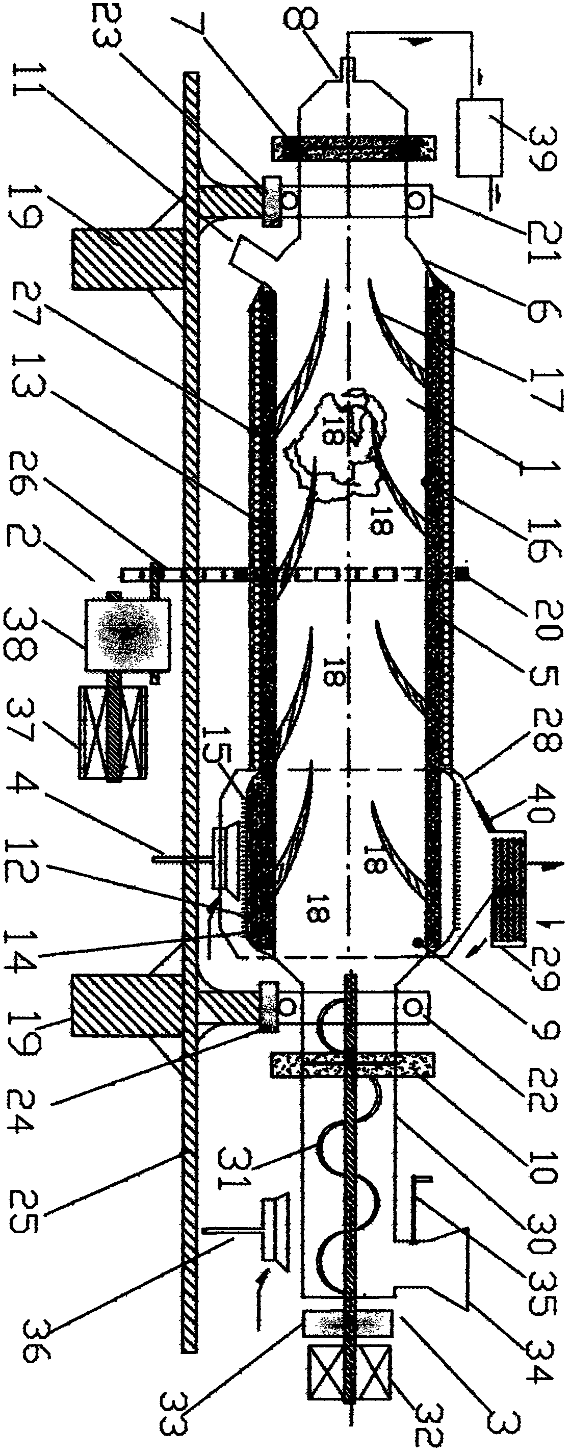
[0022] A horizontal double-tube rotary superconducting garbage pyrolysis gasifier is composed of a double-tube furnace body 1, a furnace body rotary drive 2, a feeder 3 and a burner 4. It is characterized in that the double-layer tube furnace body 1 is a double-layer cylinder in which two circular tubes are sheathed together, and a vacuum superconducting cavity 5 sealed at both ends is formed between the two layers of the double-layer cylinder. The left end 6 of the double-layer tube furnace body is conical truncated, the left end 6 is connected to the gas outlet 8 through the sealing ring 7, the right end 9 is conical, and the right end 9 is connected to the feeder 3 through the sealing ring 10. Between the two layers of the right end 9 round tables is a heating pool 12, the superconducting cavity 5 communicates with the heating pool 12, the inner surface is equipped with a superconducting liquid-absorbing core 13, and the heating pool 12...


PUM

PropertyMeasurementUnit
Thermal conductivityaaaaaaaaaa
Heat resistance temperatureaaaaaaaaaa
Thicknessaaaaaaaaaa

Abstract

The invention provides a horizontal double-layer tube rotary superconducting waste pyrolysis gasifier, which is composed of four parts of a double-layer tube gasifier body, a gasifier body rotary driver, a feeder and a burner. The horizontal double-layer tube rotary superconducting waste pyrolysis gasifier is characterized in that the double-layer tube gasifier body is a round cylinder with two round tubes sleeving together, a superconducting cavity and heating tank with the two ends sealed are formed between the two layers of the round cylinder, the superconducting cavity and the heating tankcommunicate an inner surface installed liquid absorbing coreand a high-temperature superconducting working medium, heat exchanging fins are installed around the heating tank, and stirring plates areinstalled on the inner walls of the heating tank and the superconducting cavity. Radiant heat generated by heating the rotary gasifier body outside the gasifier body with fuel gas produced by the waste pyrolysis gasifier for the burner is rapidly and uniformly transmitted to waste in the gasifier body through the heating tank, the high-temperature superconducting working medium, the superconducting liquid absorbing core and the superconducting cavity to complete efficient pyrolysis and gasification of the waste. According to the horizontal double-layer tube rotary superconducting waste pyrolysis gasifier, external heating of the pyrolysis furnaceis conducted, the temperature of a waste high-temperature reaction zone is constant, the risks of adhesion, bulking, blocking and coking due to local overheating of the waste in the gasifier body in traditional pyrolysis furnaces are avoided, releasing of harmful pyrolysates is shielded, production of dioxin is inhibited, pyrolytic solid residue can be used as activated carbon to make chemical raw materials, and comprehensive economic benefits are high.

Description

Technical field: [0001] The invention relates to a domestic waste treatment device, in particular to a low-energy-consumption and high-efficiency horizontal double-tube rotary superconducting waste pyrolysis gasifier. Background technique [0002] The disposal of municipal solid waste has become an important task for the coordinated development of energy, environment and society, and an important and urgent task for governments at all levels in our country. [0003] Pyrolysis and gasification of domestic waste is an advanced technology to realize waste reduction, harmlessness, and recycling. Today, when "garbage siege" has become a public hazard, the use of pyrolysis and gasification technology to treat waste has been highly valued by countries all over the world and the Chinese government. [0004] The pyrolysis gasification of garbage is to put domestic garbage in a specific equipment, and under a certain temperature and pressure, make a series of chemical reactions betwee...

Claims


Application Information

Patent Timeline
IPC IPC(8): F23G5/027F23G5/20F23G5/32F23G5/44F23G5/46
CPCF23G5/027F23G5/20F23G5/32F23G5/444F23G5/46F23G2201/30F23G2201/40F23G2205/121
Inventor 田海金
Owner 西安美润环保工程技术有限公司
Learn More