
A coil stamping feeder

A feeder and coil material technology, applied in the field of stamping and feeding devices, can solve the problems of inconvenient coil stamping, affecting stamping quality, inconvenient coiling, etc., and achieve the effect of saving manpower, convenient and fast feeding, and smooth rotation

Active Publication Date: 2021-04-16
南通威锋重工机械有限公司
View PDF8 Cites 0 Cited by
  • Summary
  • Abstract
  • Description
  • Claims
  • Application Information

AI Technical Summary

Problems solved by technology

[0003] However, the traditional coil stamping feeder is inconvenient to push the coil material into the feeding frame during use, and it is inconvenient to stamp the coil material, and the impurities on the coil material will also affect the stamping quality

Method used


Image

  • A coil stamping feeder
  • A coil stamping feeder
  • A coil stamping feeder

Examples


Embodiment Construction

[0026] In order to make the technical means, creative features, goals and effects achieved by the present invention easy to understand, the present invention will be further described below in conjunction with specific embodiments.

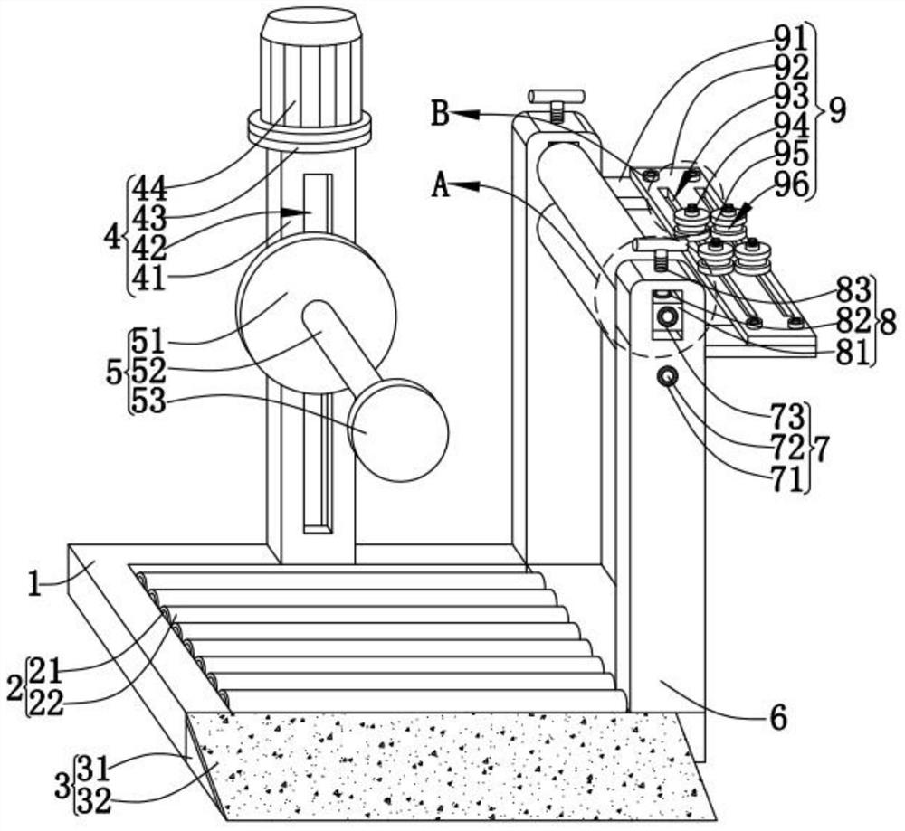
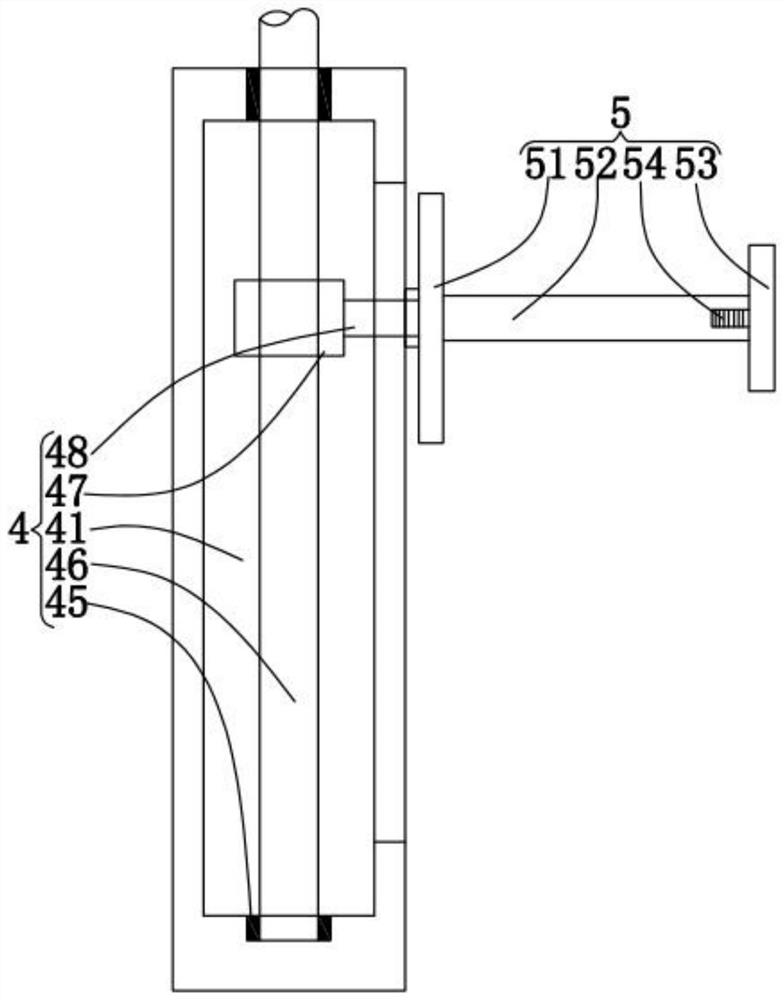
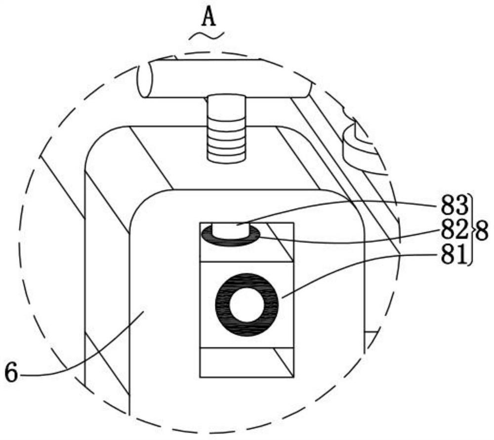
[0027] like Figure 1-Figure 4 As shown, a coil stamping feeder according to the present invention includes a base 1, a rolling structure 2, a feeding structure 3, a lifting structure 4, a rotating structure 5, a support rod 6, a cleaning structure 7, an adjusting structure 8 and a limiter. Position structure 9; the inner rotation of the base 1 for fixing and supporting is connected with the rolling structure 2 for temporarily placing the coiled material, and one end of the base 1 is provided with a device for rolling the coiled material into the rolling structure 2 The feeding structure 3; the top of the base 1 is provided with the lifting structure 4 for lifting the coiled material, and one end of the lifting structure 4 is rotatably connected w...


PUM


Abstract

The invention relates to the field of punching and feeding devices, specifically a coil punching and feeding machine, including a base, a rolling structure, a feeding structure, a lifting structure, a rotating structure, a support rod, a cleaning structure, an adjusting structure and a position limiting structure; the base The internal rotation of the base is connected with a rolling structure, and one end of the base is provided with a feeding structure that assists the roll material to roll on the rolling structure. The combination of the rolling structure and the feeding structure can enable the roll material to be pushed onto the rotating structure more labor-saving. There is no need to use a forklift or other tools to load the material, which is more convenient and fast. The top of the base is vertically connected with a lifting structure. There can be a certain gap, so that there will be no friction between the rolling structure and the coil material, so that the rotation of the rotating structure will be smoother, and the lifting structure is driven by a motor, which does not require manual lifting of the material, saving manpower.

Description

technical field [0001] The invention relates to the field of punching and feeding devices, in particular to a coil punching and feeding machine. Background technique [0002] Stamping is a forming processing method that applies external force to plates, strips, pipes and profiles by presses and molds to cause plastic deformation or separation to obtain workpieces (stamping parts) of required shape and size. Stamping and forging belong to plastic processing (or pressure processing) and are collectively called forging. The blanks for stamping are mainly hot-rolled and cold-rolled steel sheets and strips. Among the steel products in the world, 60-70% are plates, most of which are stamped into finished products. The body, chassis, fuel tank, radiator fins of the car, the steam drum of the boiler, the shell of the container, the iron core silicon steel sheet of the motor and electrical appliances, etc. are all stamped. There are also a large number of stamping parts in product...

Claims


Application Information

Patent Timeline
Patent Type & Authority Patents(China)
IPC IPC(8): B21C43/00B21D43/00
CPCB21C43/00B21D43/00B21D43/003
Inventor 宫帅陈伟光赵文富
Owner 南通威锋重工机械有限公司
Learn More