Copper pipe continuous bending device with discharging ejection device

A technology of bending device and copper tube, which is applied in the direction of feeding device, positioning device, storage device, etc., can solve the problems of poor heat dissipation, lack of ejection device, and increased labor intensity of workers in the bending machine, so as to reduce labor intensity, The effect of increasing safety and increasing practicality

Pending Publication Date: 2019-03-08
XINGHUA CHUNDA COPPER IND
View PDF0 Cites 12 Cited by
  • Summary
  • Abstract
  • Description
  • Claims
  • Application Information

AI Technical Summary

Problems solved by technology

[0004] Aiming at the deficiencies of the prior art, the present invention provides a continuous bending device for copper tubes with a material ejection device, which has the advantages of material ejection, adjustable bending angle and good heat dissipation, and solves the existing problems The bending device lacks the ejector device for discharging the material, which leads to the need for manual processing after the copper pipe is bent. This working method not only increases the labor intensity of the workers, but also reduces the working efficiency of the bending machine, and the existing The bending angle of the bending machine is mostly fixed, which cannot meet the processing requirements of different angles. In addition, the existing bending machine has poor heat dissipation during use, which affects the practicality of the bending machine.

Method used


Image

  • Copper pipe continuous bending device with discharging ejection device
  • Copper pipe continuous bending device with discharging ejection device
  • Copper pipe continuous bending device with discharging ejection device

Examples


Embodiment Construction

[0024] The following will clearly and completely describe the technical solutions in the embodiments of the present invention with reference to the accompanying drawings in the embodiments of the present invention. Obviously, the described embodiments are only some, not all, embodiments of the present invention. Based on the embodiments of the present invention, all other embodiments obtained by persons of ordinary skill in the art without making creative efforts belong to the protection scope of the present invention.

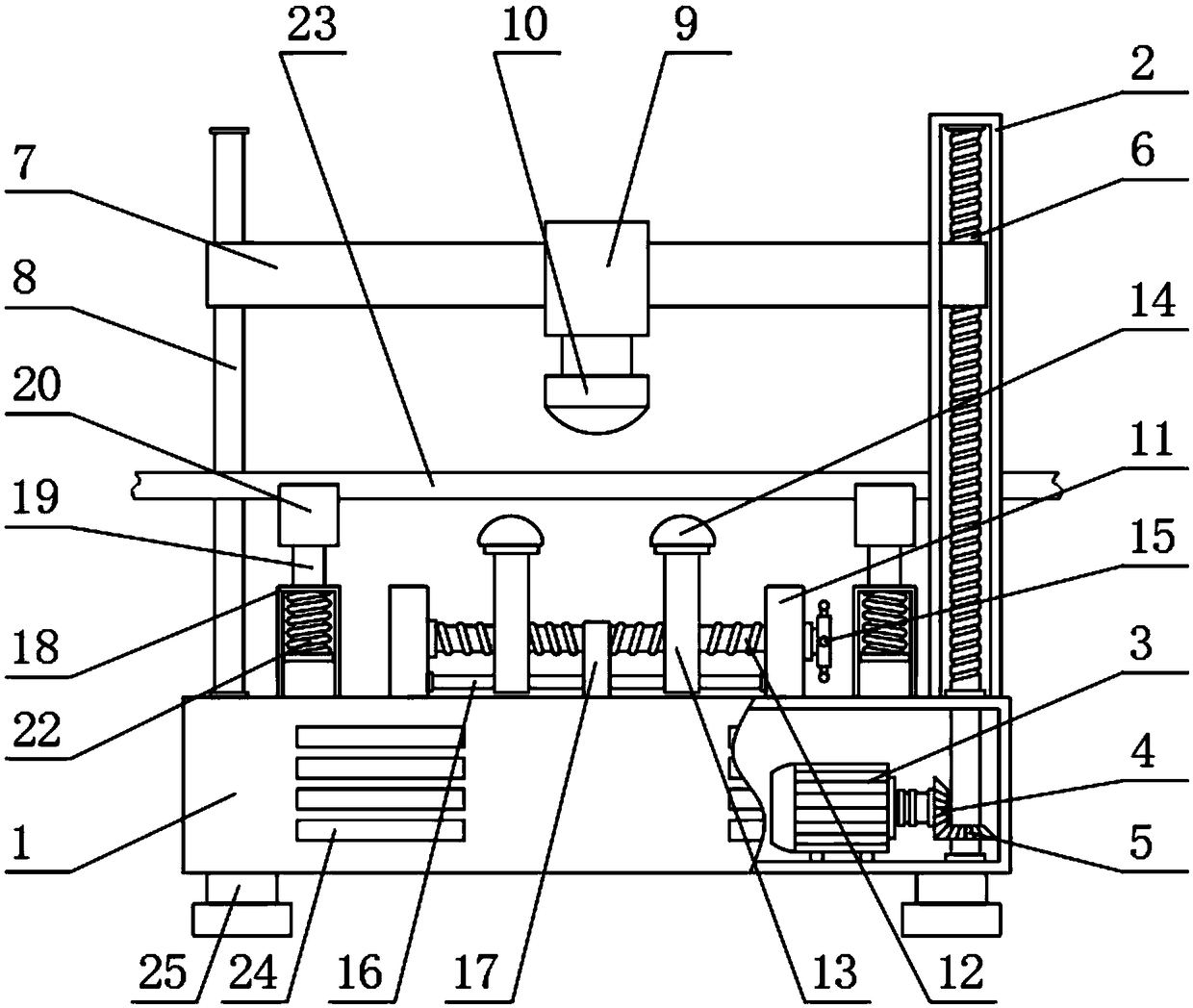
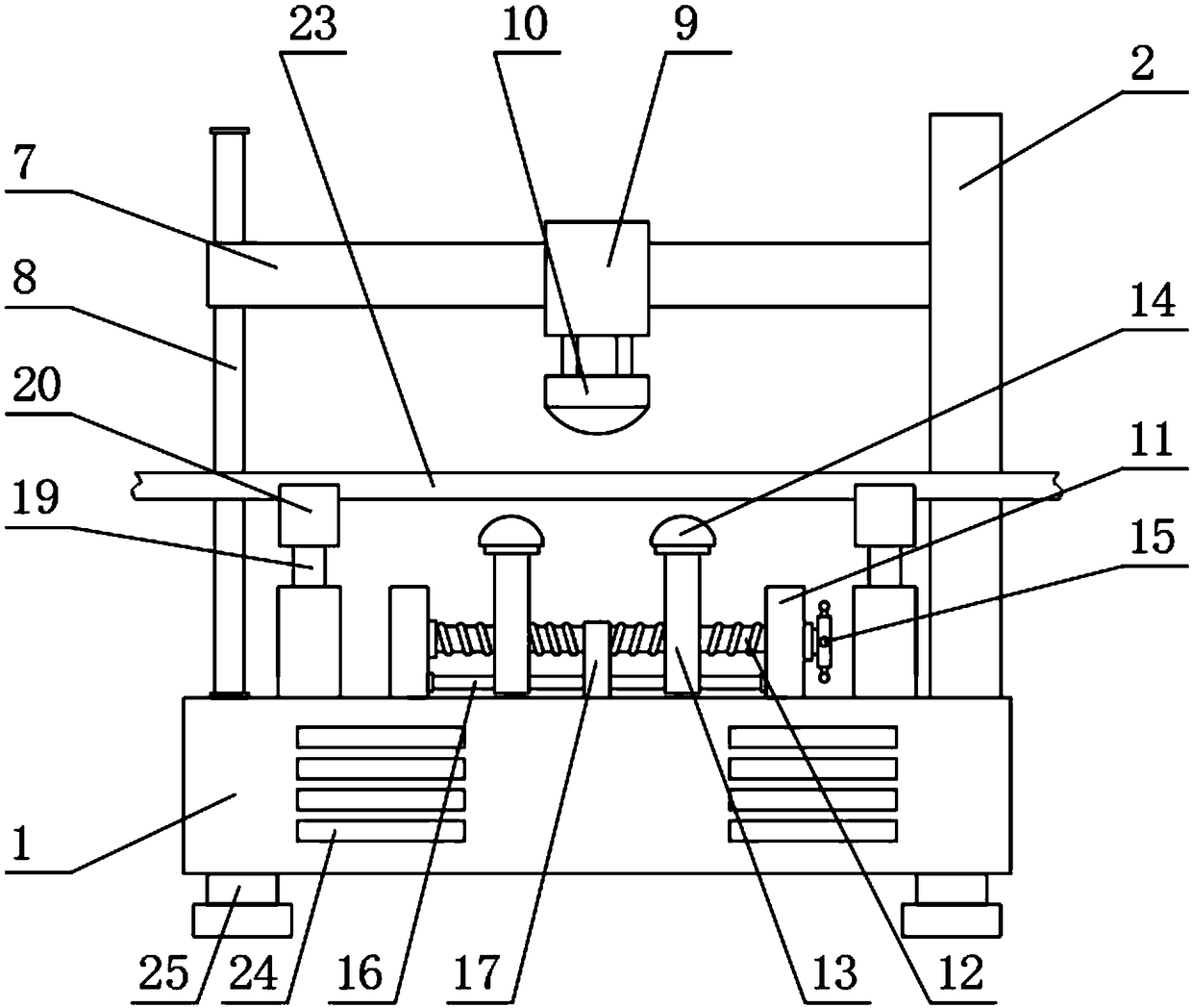
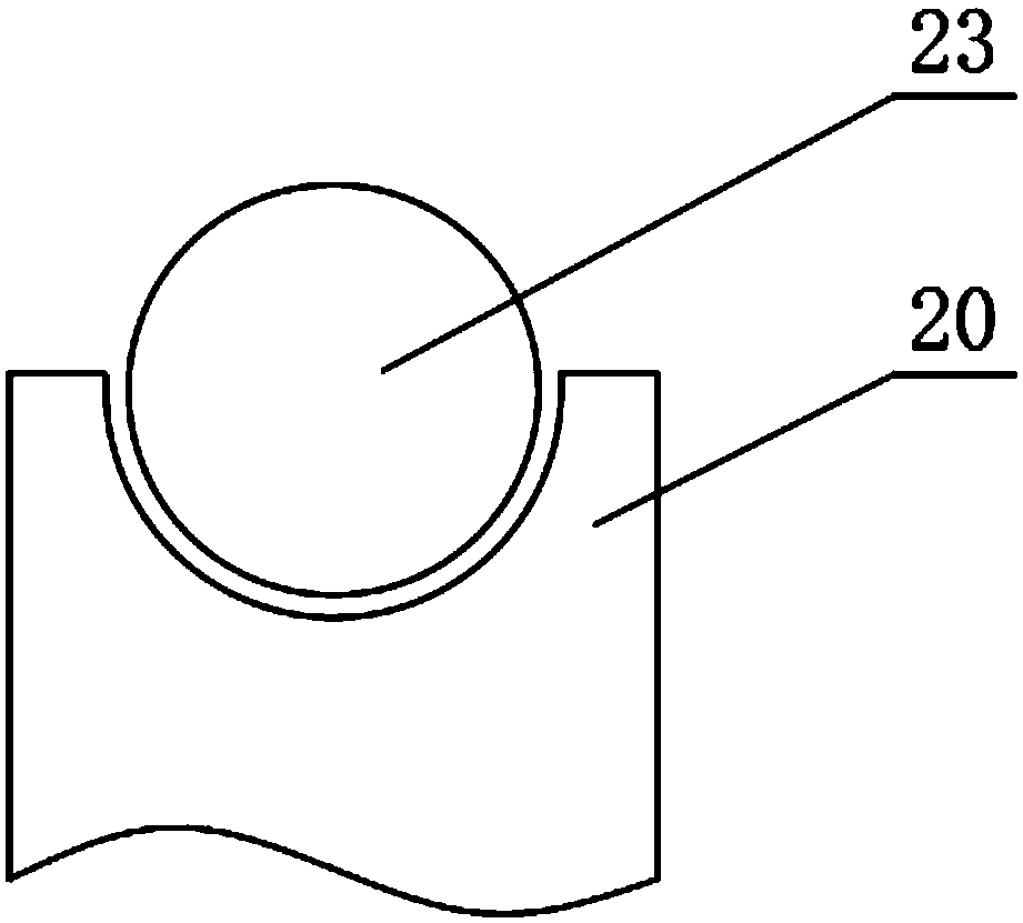
[0025] see Figure 1-4 , a continuous bending device for copper tubes with a material ejection device, comprising a body 1, the bottom of the body 1 is fixedly equipped with support legs 25, the number of support legs 25 is four, and the four cooling grooves 24 are equally divided It is two groups, and two groups of cooling grooves 24 are respectively located at both sides of the bottom of the body 1, the right side of the top of the body 1 is fixedly installe...


PUM


Abstract

The invention relates to the technical field of bending devices, and discloses a copper pipe continuous bending device with a discharging ejection device. The copper pipe continuous bending device comprises a machine body; a right supporting rod is fixedly installed on the right side of the top of the machine body, a motor is fixedly installed at the bottom of an inner cavity of the machine body,and a master gear is fixedly arranged on an output shaft of the motor in a sleeve mode; and the bottom end of the main gear is connected to a sub-gear in a meshed mode, a screw rod is fixedly arrangedin the middle of the sub-gear in a sleeve mode, the top end of the screw rod penetrates through the right supporting rod to extend into the interior of the right supporting rod, and a connecting rodpositioned inside the right supporting rod is arranged on the outer surface of the screw rod in a threaded mode. According to the copper pipe continuous bending device with the discharging ejection device, an ejection rod, an ejection head and an ejection spring are arranged, when the bending is completed, an upper bending head is separated from a copper pipe, the acting force of the ejection spring pushes the ejection rod and the ejection head to rise, so that the copper pipe is ejected out, and the labor intensity of workers is reduced.

Description

technical field [0001] The invention relates to the technical field of bending devices, in particular to a continuous bending device for copper pipes with a material ejection device. Background technique [0002] Copper tubes are also called copper tubes. Copper tubes have good electrical conductivity and thermal conductivity. They are the main materials for conductive accessories and heat dissipation accessories of electronic products, and have become the tap water pipes, heating, and First choice for refrigeration piping installations. [0003] Copper pipes often need to be bent with bending devices in the actual application process. The existing bending devices lack ejection devices for discharging materials, resulting in the need for manual processing after the copper pipes are bent. This working method It not only increases the labor intensity of workers, but also reduces the working efficiency of the bending machine, and the bending angle of the existing bending machi...

Claims


Application Information

Patent Timeline
Patent Type & Authority Applications(China)
IPC IPC(8): B21D7/06B21D37/16B21D45/04B21D43/00
CPCB21D7/06B21D37/16B21D43/003B21D45/04
Inventor 王慧
Owner XINGHUA CHUNDA COPPER IND
Why Eureka
Try Eureka