Waste sand calcining system
A roasting and sand feeding technology, which is used in foundry molding equipment, machinery for cleaning/processing of casting materials, metal processing equipment, etc. energy, reduced heating time, evenly distributed effect
- Summary
- Abstract
- Description
- Claims
- Application Information
AI Technical Summary
Problems solved by technology
Method used
Image

Examples
Embodiment 1
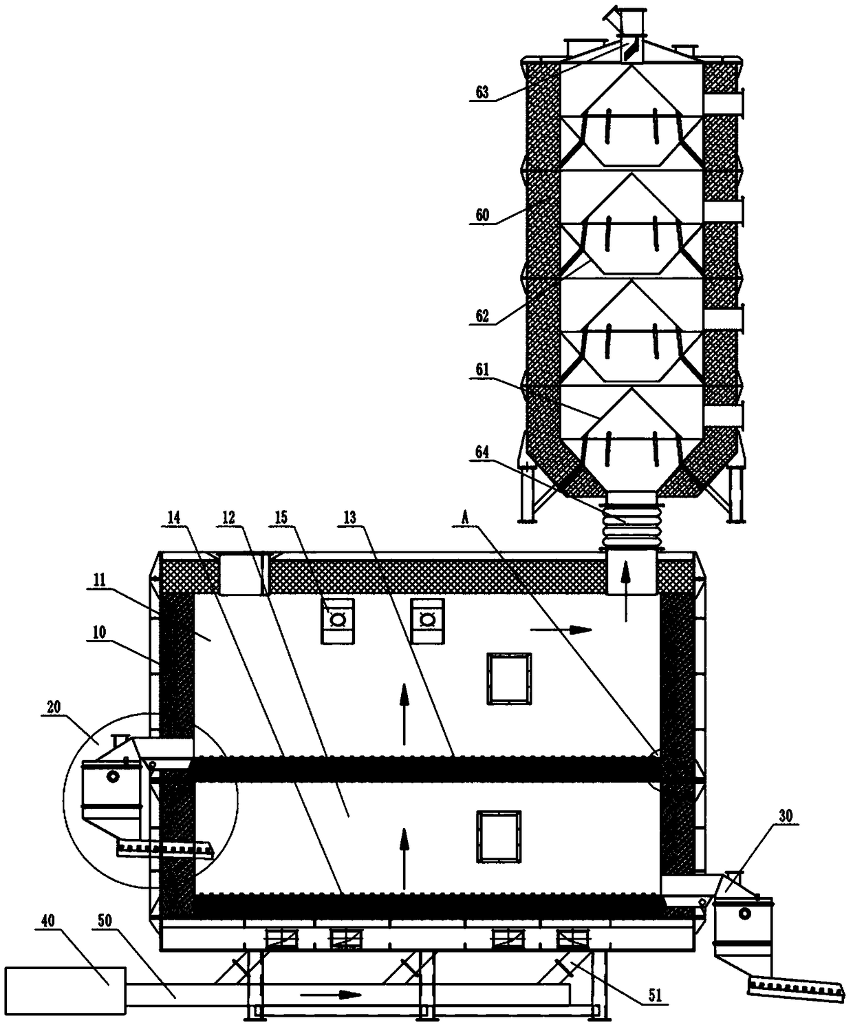
[0034] The embodiment is basically as attached figure 1 Shown: a waste sand roasting system, including a drying tower 60, a furnace body 10, and an air intake unit connected to the bottom of the furnace body 10. The furnace body 10 includes a ceramic fiber cotton heat-insulating refractory layer. The drying tower 60 is located above the right side of the furnace body 10 , and a bellows 64 communicates between the lower end of the drying tower 60 and the upper part of the furnace body 10 . The upper part of the drying tower 60 is connected with a feed pipe 63. There are multiple sets of dispersing parts along the height direction inside the drying tower 60. The dispersing parts include an inverted V-shaped dispersing plate 61 and two symmetrically arranged aggregates that form an inverted figure-eight shape. plate 62 , the collecting plate 62 is located below the dispersing plate 61 .
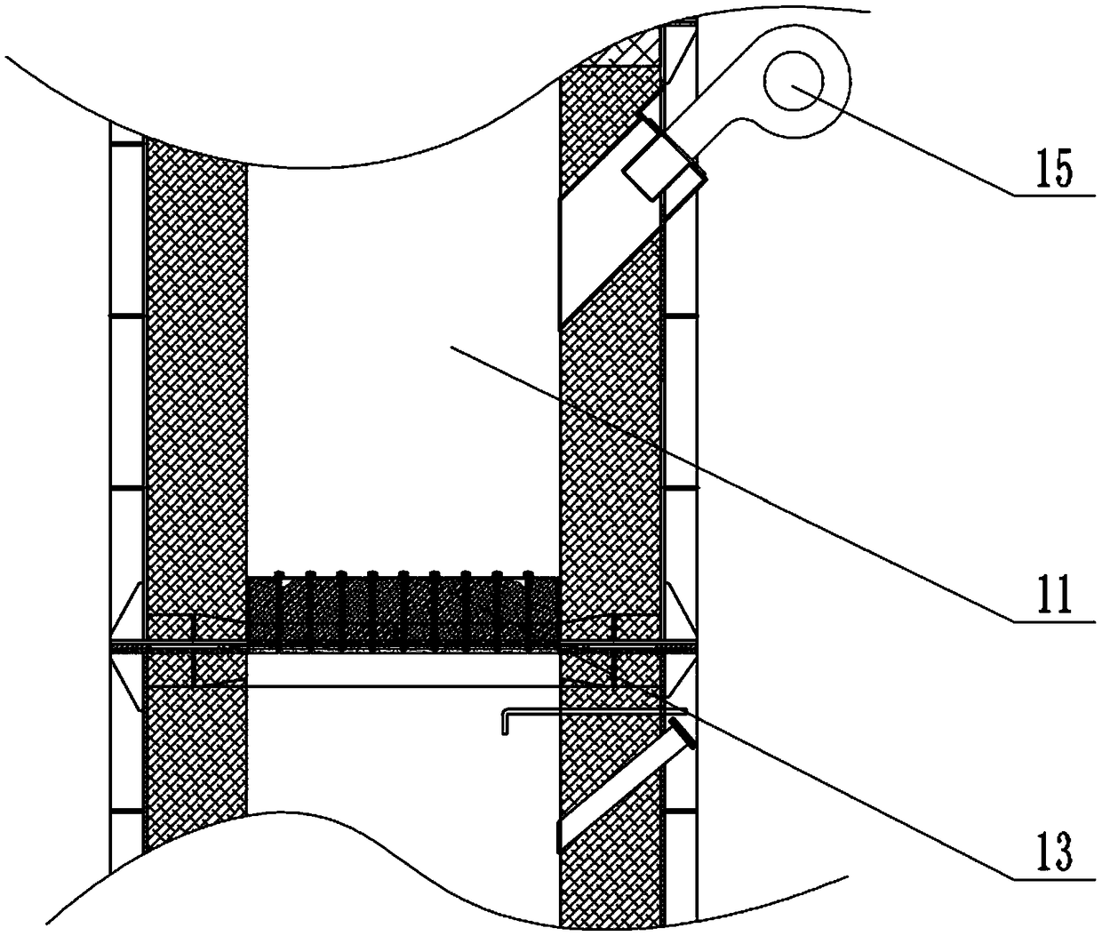
[0035] combine figure 2 As shown, the side wall of the furnace body 10 is fixedly install...
Embodiment 2
[0042] The difference between this embodiment and Embodiment 1 is that the waste sand roasting system also includes a first controller; the sand level control mechanism includes a first blower communicated with the air chamber 23 and a material level gauge arranged in the closed box 21, the first The controller is electrically connected to the first air blower and the material level gauge in the two sand level control mechanisms.
[0043] When the sand level in the upper closed box is higher than the preset value, the first controller receives the signal sent by the material level gauge in the upper closed box, and the first controller controls the first blower connected with the air chamber 23 of the upper sand delivery pipe Work, send the spent sand in the sand pipe and flow down the roasting layer 12. And when the sand level in the last closed box was lower than the prescribed height, the first controller received the signal sent by the material level gauge in the last clos...
Embodiment 3
[0047] The difference between this embodiment and Embodiment 1 is that the waste sand roasting system also includes a second controller and a second blower, and a pipeline (hereinafter referred to as the first pipeline) is connected between the second blower and the air chamber 23 of the sand sending pipe. ), the second air blower is connected with pipeline (hereinafter referred to as the second pipeline) between the air chamber 23 of the sand pipe, the first pipeline is provided with the first valve, and the second pipeline is provided with the second valve. The sand level control mechanism is a material level gauge located in the closed box 21, and the second controller is electrically connected with the first valve, the second valve and the material level gauges in the two sand level control mechanisms. The air inlet unit includes a main pipe 50 , a third pipe is connected between the main pipe 50 and the second blower, and multiple air inlet branch pipes 51 are connected be...
PUM
 Abstract
Description
Claims
Application Information
 - Generate Ideas
- Intellectual Property
- Life Sciences
- Materials
- Tech Scout
- Unparalleled Data Quality
- Higher Quality Content
- 60% Fewer Hallucinations
Browse by: Latest US Patents, China's latest patents, Technical Efficacy Thesaurus, Application Domain, Technology Topic, Popular Technical Reports.
© 2025 PatSnap. All rights reserved.Legal|Privacy policy|Modern Slavery Act Transparency Statement|Sitemap|About US| Contact US: help@patsnap.com