
A new energy vehicle tire

A new energy vehicle and tire technology, applied in the direction of wheels, wheel accessories, vehicle parts, etc., can solve the problems of increased tire rotation speed, longer braking distance, slippage, etc., to reduce sliding distance, increase resistance, and increase the effect of braking effect.

Active Publication Date: 2020-08-28
罗帮亮
View PDF8 Cites 0 Cited by
  • Summary
  • Abstract
  • Description
  • Claims
  • Application Information

AI Technical Summary

Problems solved by technology

[0003] New energy vehicles can increase to a very high speed in a short period of time, and the speed of the tires will increase at the same time. In a low temperature environment, a layer of ice will form on the road surface, especially in winter, the icy road surface will cause the car to brake or start. Skidding occurs at times, and the braking distance becomes longer at the same time, resulting in a large number of accidents

Method used


Image

  • A new energy vehicle tire
  • A new energy vehicle tire

Examples


Embodiment Construction

[0016] The following will clearly and completely describe the technical solutions in the embodiments of the present invention with reference to the accompanying drawings in the embodiments of the present invention. Obviously, the described embodiments are only some, not all, embodiments of the present invention.

[0017] In describing the present invention, it should be understood that the terms "upper", "lower", "front", "rear", "left", "right", "top", "bottom", "inner", " The orientation or positional relationship indicated by "outside", etc. is based on the orientation or positional relationship shown in the drawings, and is only for the convenience of describing the present invention and simplifying the description, rather than indicating or implying that the referred device or element must have a specific orientation, so as to Specific orientation configurations and operations, therefore, are not to be construed as limitations on the invention.

[0018] refer to Figure ...


PUM


Abstract

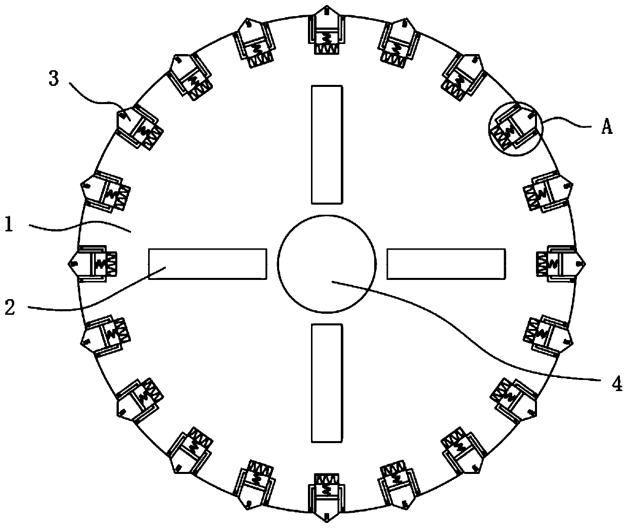
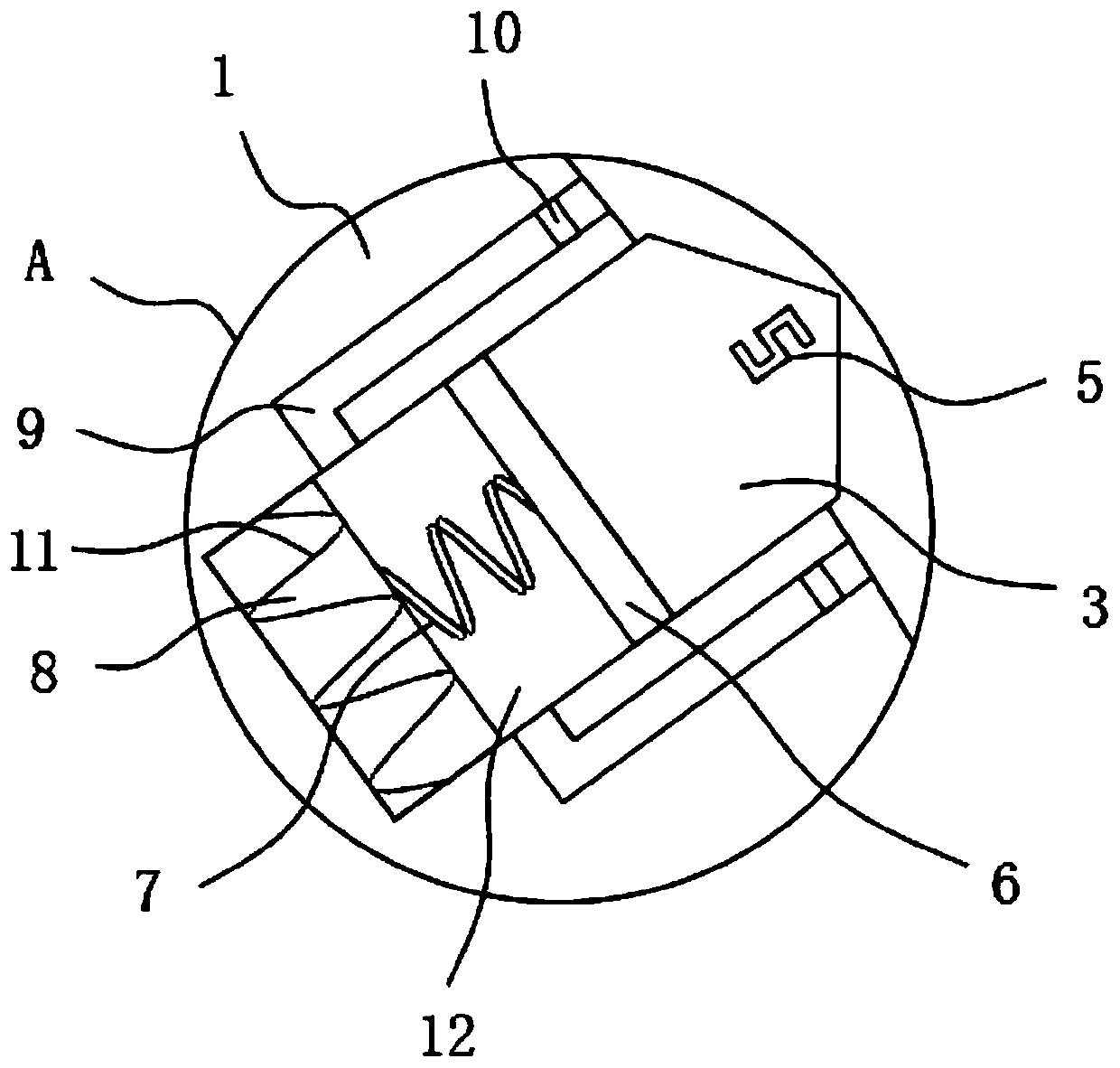
The invention discloses a tire for a new energy vehicle. The tire comprises a rotating shaft installed in the tire crown center, a hub is fixedly connected to one end of the rotating shaft, four thermoelectric couples in an annular array are arranged on the hub, multiple cavities in an annular array by taking the rotating shaft as the center are arranged on the hub at equal intervals, second magnets are fixedly connected to the side walls, close to the rotating shaft, of the cavities, magnet exciting coils wind around the second magnets, stop pins are slidably connected to the interiors of thecavities, first magnets are fixedly connected to the ends, close to the second magnets, of the stop pins, and springs are fixedly connected to one sides of the second magnets. Accordingly, by means of interaction of the thermoelectric couples, electrical heating elements, the first magnets, the springs, the second magnets, the magnet exciting coils and other structures, the stop pins can enter anice layer when the tire rotates, resistance of the tire is increased when braking is conducted, and the sliding distance in the braking process is reduced.

Description

technical field [0001] The invention relates to the technical field of automobile tires, in particular to a tire for new energy automobiles. Background technique [0002] With the development of science and technology, environmental protection and energy saving are the top priorities of national development. New energy, as an environmentally friendly energy, has become a new driving force for automobiles. In addition, the development of other components of new energy vehicles is also ongoing. [0003] New energy vehicles can increase to a very high speed in a short period of time, and the speed of the tires will increase at the same time. In a low temperature environment, a layer of ice will form on the road surface, especially in winter, the icy road surface will cause the car to brake or start. Occasionally skidding occurs, and the braking distance becomes longer at the same time, causing a large number of accidents. Contents of the invention [0004] The purpose of the...

Claims


Application Information

Patent Timeline
Patent Type & Authority Patents(China)
IPC IPC(8): B60B15/00B60B19/00
CPCB60B15/00B60B19/00
Inventor 岳广琴
Owner 罗帮亮
Learn More