
Dynamic display time threshold plate based on programmability

A technology of dynamic display and sill plate, applied in door lighting devices, lighting circuits, passenger/cab lighting, etc., can solve problems such as monotony, and achieve flexible adaptability, strong dynamic adjustability, and gorgeous decorative effects

Active Publication Date: 2019-03-08
SHANGHAI YINGHUI TECH DEV
View PDF8 Cites 0 Cited by
  • Summary
  • Abstract
  • Description
  • Claims
  • Application Information

AI Technical Summary

Problems solved by technology

[0003] However, the traditional luminous sill plate can only produce static monochrome luminous effect, which is relatively monotonous. In response to the continuous demand of the automobile market, there are more and more patterns of automobile decoration atmosphere products, and the effect is getting better and better. It is urgent to develop more gorgeous and decorative effects. Better LED Luminous Threshold Plates

Method used


Image

  • Dynamic display time threshold plate based on programmability
  • Dynamic display time threshold plate based on programmability
  • Dynamic display time threshold plate based on programmability

Examples


Embodiment 1

[0055] The specific operation steps of embodiment 1 are as follows:

[0056] First, burn the software program part that needs to realize the streamer effect into the main control chip through the software program input terminal (that is, the P2 port is the online program burning port);

[0057] Secondly, the LED lamp beads are arranged in two strings and multiple parallel connections, and the number of lamp beads to be used is determined according to the lighting length of the product of the present invention according to customer needs; each series branch controls the working current of the circuit through a current-limiting resistor , An NPN (8050) triode controls the opening and closing of the circuit.

[0058] Then, turn on the power supply through the control of the body side (in practice, it can start to turn on the power supply when the owner opens the door), that is, the 12V body voltage passes through the 78L05 voltage regulator tube (that is, belongs to the circuit v...

Embodiment 2

[0075] The specific operation steps of embodiment 2 are as follows:

[0076] First, burn the software program part that needs to realize the streamer effect into the main control chip through the software program input terminal (that is, the P2 port is the online program burning port);

[0077] Secondly, the LED lamp beads are arranged in a single-string multi-parallel connection method, and the number of lamp beads used is determined according to the lighting length of the product of the present invention according to customer needs; the lamp beads can be in the form of two-color or RGB to realize switching of more colors Function; each series branch controls the working current of the circuit through a current-limiting resistor, and a MOS tube controls the on-off of a single color on one side; the PWM output function of the main control chip controls the breaking time, working frequency, and brightness of the MOS tube. The off-duty cycle can realize the slow on and off effec...


PUM


Abstract

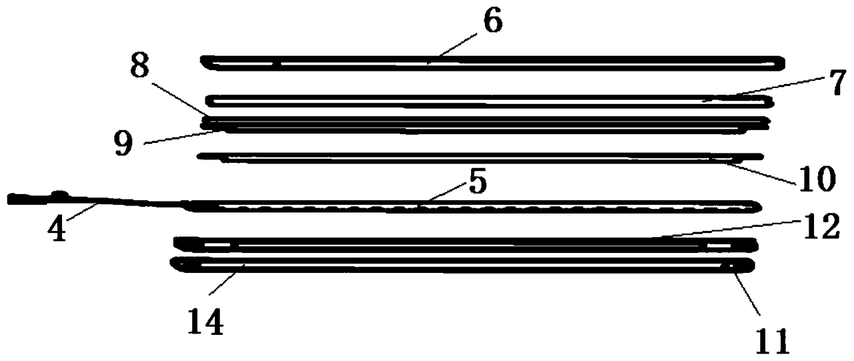
The invention relates to the field of car trims, in particular to a dynamic display time threshold plate based on programmability. The dynamic display time threshold plate comprises a threshold platebody and a time module, and is characterized in that the time module is placed in the threshold plate body, and the time effect is displayed externally through a light-permeable part on the thresholdplate body, the time module is composed of a main circuit control unit, a controlled unit and a software program, the main circuit control unit is composed of a main control chip, a PCB and a wire harness assembly, and the controlled unit is composed of at least one lamp beads and a PCB. By means of the threshold plate, the problems that a traditional light-emitting threshold plate in the prior art can only have a static single-color light-emitting effect and is relatively monotonous and the threshold plate cannot realize the dynamic display time effect under the control of the software program are solved.

Description

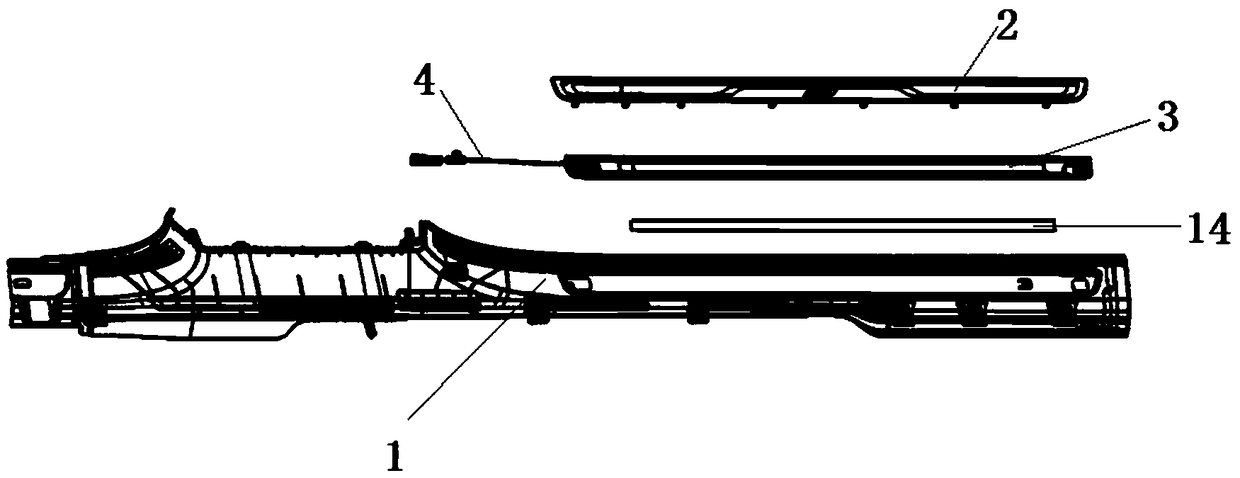
technical field [0001] The invention relates to the field of automobile decoration parts, in particular to a programmable-based dynamic display streamer threshold plate. Background technique [0002] At present, the LED (light-emitting diode) light-emitting sill plate is a kind of LED component used to decorate the lower part of the automobile door panel. After the door is opened, the decorative panel will statically display the pattern of the light-emitting area in monochrome, such as the abbreviation of the model name or the shape of the decorative bright strip, which mainly plays a role in beautifying the decoration and also plays the role of auxiliary lighting at night. When the user opens the car door, he sees a gorgeous pattern shining from below, which has a high-end and fashionable feeling, and can also have a good driving mood. [0003] However, the traditional luminous sill plate can only produce static monochrome luminous effect, which is relatively monotonous. I...

Claims


Application Information

Patent Timeline
Patent Type & Authority Applications(China)
IPC IPC(8): B60Q3/217B60Q3/80
CPCB60Q3/217B60Q3/80
Inventor 童鑫鑫徐强张文明李妍朱建忠郝佳佳陆路何寅伟
Owner SHANGHAI YINGHUI TECH DEV
Learn More