Hydraulic anchor rod trolley

An anchor trolley and hydraulic technology, applied in the field of tunnel construction machinery and mining, can solve the problems of heavy load bearing, hidden safety hazards, and large required space of the mechanical arm, and achieve the effect of ensuring rigidity, strength and stability.

Pending Publication Date: 2019-03-08
河南省耿力工程设备有限公司
View PDF0 Cites 27 Cited by
  • Summary
  • Abstract
  • Description
  • Claims
  • Application Information

AI Technical Summary

Problems solved by technology

The existing hydraulic rock bolting jumbo is only used for bolting operations, and the hydraulic rock drilling jumbo is only used for rock drilling operations, and the two cannot be interchanged or replaced
When the roadheader operation is completed, the support operator needs to move the rock bolter to the newly exposed empty roof area to install the drill pipe or anchor rod, and perform anchor rod and anchor cable support for the newly exposed roof and two sides After the support is completed, move the bolter to a safe place in the back, so that each cycle needs to dismantle and install the equipment, which is repeated many times per shift, which is very troublesome and time-consuming...

Method used


Image

  • Hydraulic anchor rod trolley
  • Hydraulic anchor rod trolley
  • Hydraulic anchor rod trolley

Examples


Embodiment Construction

[0024] The implementation of the present invention will be illustrated by specific specific examples below, and those skilled in the art can easily understand other advantages and effects of the present invention from the contents disclosed in this specification.

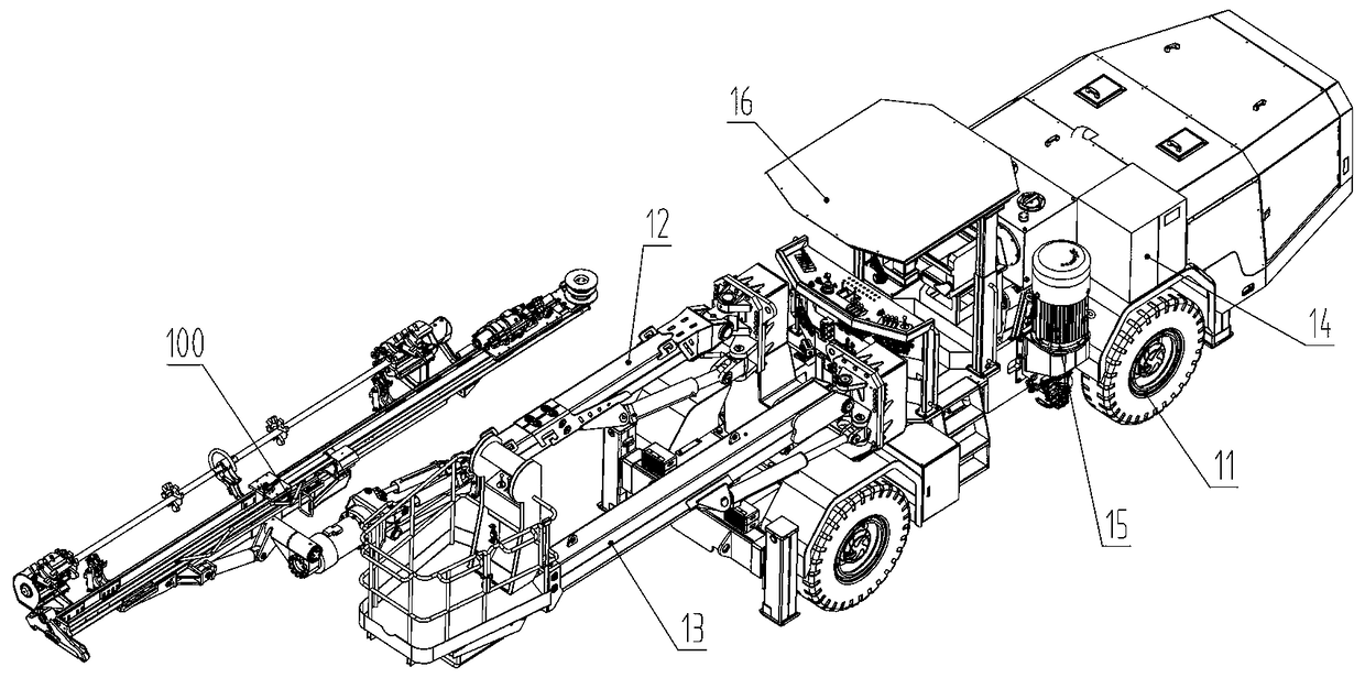
[0025] see figure 1. The structures, proportions, sizes, etc. shown in the drawings attached to this specification are only used to cooperate with the content disclosed in the specification, for those who are familiar with this technology to understand and read, and are not used to limit the conditions for the implementation of the present invention. Therefore, there is no technical substantive meaning, and any modification of structure, change of proportional relationship or adjustment of size shall still fall within the scope of the disclosure of the present invention without affecting the functions and objectives of the present invention. within the scope of technical content. At the same time, terms such as "u...


PUM


Abstract

The invention discloses a hydraulic anchor rod trolley, which comprises an engineering chassis, a working arm, an auxiliary arm, an anchor rod mechanism, an electrical system, a hydraulic system and acab. The anchor rod mechanism comprises a propulsion beam and a rock drill, an anchor rod bin is arranged on one side of the propulsion beam, a sliding guide rail, a caliper device, a rod grabbing device and a rod mounting device are arranged on the propulsion beam, the rod mounting device transfers a drill pipe or an anchor rod between the caliper device and the anchor rod bin, the rock drill isslidably connected with thesliding guide rail, and comprises a first sliding base, a power device, an output shaft and a connecting sleeve, the power device drives the output shaft to rotate, the output shaft is matched with one end of the connecting sleeve in a threaded mode, and the other end of the connecting sleeve is matched with the drill pipe or the anchor rod in a threaded mode; and the caliper device comprises a drill-rod clamping device and a drill-rod lifter which are arranged successively from front to rear. Switching between the anchor rod and drilling operation is realized on the basis of the engineering chassis, the sliding guide rail, a propulsion device and the like, and the multi-functionalization of the anchor rod trolley is realized.

Description

technical field [0001] The invention relates to the technical field of mining and tunnel engineering machinery, in particular to a hydraulic bolt trolley used for rock drilling and bolting. Background technique [0002] Bolting machine, also known as soil nailing machine, bolting rig or pneumatic impact machine, is mainly used for rock and soil bolting, roadbed, slope treatment, underground deep foundation pit support, tunnel surrounding rock stability, prevention of landslides and other disasters. Underground engineering support and high-rise building foundation treatment. It is also suitable for non-prestressed bolt support of deep foundation pit spray protection and slope soil nailing engineering. At this stage, rock drilling and bolt support construction in mines and tunnels are two different modes of operation. Existing hydraulic rock bolting jumbo is only used for bolting operation, and hydraulic rock drilling jumbo is only used for rock drilling operation, and the t...

Claims


Application Information

Patent Timeline
IPC IPC(8): E21C25/66E21D20/00E21B7/02E21B15/00
CPCE21B7/025E21B15/003E21C25/66E21D20/003
Inventor 徐建华杨帅岭黄圣英
Owner 河南省耿力工程设备有限公司
Why Eureka
Try Eureka