
A near-field heat reflection measuring device

A measuring device and technology of heat reflection, applied in the direction of material thermal development, material thermal conductivity, etc., can solve the problem that the influence of the beam transmission orientation cannot be reduced.

Active Publication Date: 2021-05-11
INST OF ELECTRICAL ENG CHINESE ACAD OF SCI
View PDF8 Cites 0 Cited by
  • Summary
  • Abstract
  • Description
  • Claims
  • Application Information

AI Technical Summary

Problems solved by technology

[0005] In view of this, the embodiment of the present invention proposes a near-field heat reflection measurement device to solve the problem that the existing heat reflection measurement device can only reduce the influence of environmental vibration, but cannot reduce the instability caused by each optical component itself. The problem of the influence on the beam transmission orientation

Method used


Image

  • A near-field heat reflection measuring device
  • A near-field heat reflection measuring device

Examples


Embodiment Construction

[0022] The technical solutions of the present invention will be clearly and completely described below in conjunction with the accompanying drawings. Apparently, the described embodiments are some of the embodiments of the present invention, but not all of them. Based on the embodiments of the present invention, all other embodiments obtained by persons of ordinary skill in the art without making creative efforts belong to the protection scope of the present invention.

[0023] In the description of the present invention, it should be noted that the terms "first" and "second" are used for description purposes only, and should not be understood as indicating or implying relative importance.

[0024] In the description of the present invention, it should be noted that unless otherwise specified and limited, the terms "installation", "connection" and "connection" should be understood in a broad sense, for example, it can be a fixed connection or a detachable connection. Connected...


PUM

PropertyMeasurementUnit
diameteraaaaaaaaaa

Abstract

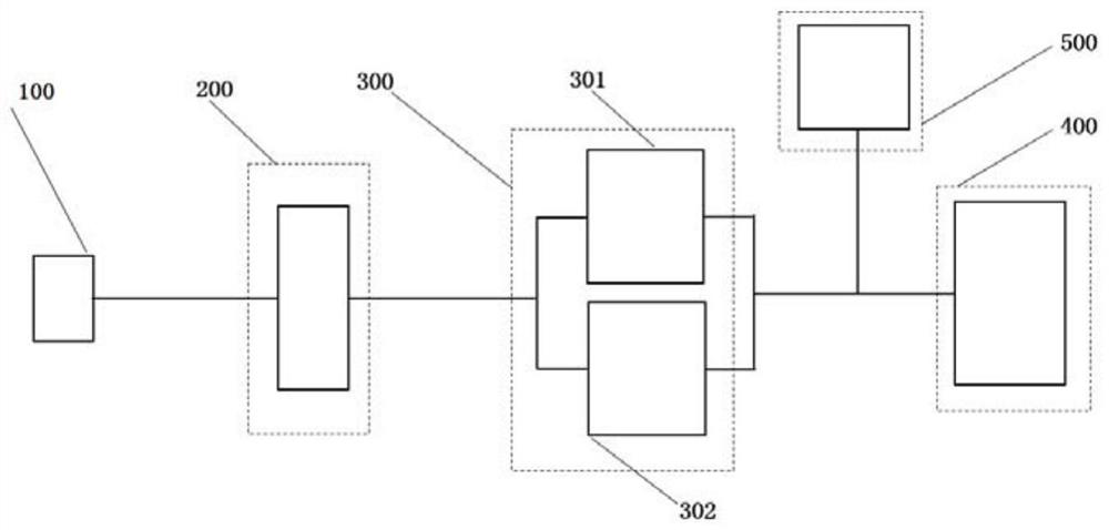
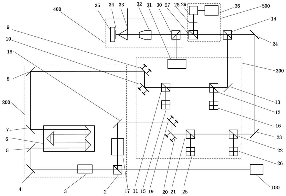
The embodiment of the present invention provides a near-field thermal reflection measurement device, the near-field thermal reflection measurement device includes: a laser generator, a beam correction system, a near-field measurement system and a computer; the laser generator emits a laser signal to the beam correction system; The beam correction system corrects the azimuth of the laser signal, and transmits the corrected laser signal to the near-field measurement system; the near-field measurement system obtains the electrical signal representing the thermal property information of the sample to be measured according to the corrected laser signal, and converts the electrical signal to the near-field measurement system. The signal is transmitted to the computer; the computer obtains the thermal property information of the sample to be tested according to the electrical signal and the light intensity of the pre-stored laser signal. By implementing the present invention, not only the influence of environmental vibration can be reduced, but also the influence on the beam transmission orientation caused by the instability of each optical component itself can be reduced, and the reliability and accuracy of the near-field thermal reflection measuring device can be ensured. Spend.

Description

technical field [0001] The invention relates to the technical field of thermal conductivity testing, in particular to a near-field heat reflection measurement device. Background technique [0002] With the reduction of the characteristic scale of microelectronics / optoelectronics and other devices, the improvement of integration and the increase of operating speed, the unit heat loss generated in the device / chip is becoming more and more serious, the temperature rise is accelerated, and the hot spot temperature is rising, which seriously affects the device / chip. performance and reliability. To this end, reasonable thermal design and material and circuit layout are required to effectively export the heat generated rapidly by the device. The measurement of the thermal physical properties of the multi-layer micro-nano films and structures that constitute the device is a key step to achieve this goal. [0003] The near-field thermal reflectance measurement device using a near-fi...

Claims


Application Information

Patent Timeline
Patent Type & Authority Patents(China)
IPC IPC(8): G01N25/20G01N25/18
CPCG01N25/18G01N25/20
Inventor 刘珠明王大正孙方远郑利兵殷伯华韩立
Owner INST OF ELECTRICAL ENG CHINESE ACAD OF SCI
Learn More