Battery test fixture and battery test tooling

A battery testing and testing splint technology, which is applied to measuring devices, measuring device housings, components of electrical measuring instruments, etc., can solve problems such as cumbersome processes, unusable aluminum rows or connecting devices, etc., to reduce material waste, Improve test efficiency and ensure the effect of test results

Pending Publication Date: 2019-03-08
成都市银隆新能源产业技术研究有限公司 +1
View PDF0 Cites 1 Cited by
  • Summary
  • Abstract
  • Description
  • Claims
  • Application Information

AI Technical Summary

Problems solved by technology

[0002] At this stage, after the assembly of lithium batteries is completed, a series of battery electrical performance and safety performance tests are required. During the test process, the battery is required to be closely connected with the test instrument to ensure the accuracy of the battery test. Weld the aluminum r

Method used


Image

  • Battery test fixture and battery test tooling
  • Battery test fixture and battery test tooling
  • Battery test fixture and battery test tooling

Examples


Example

[0033] first embodiment

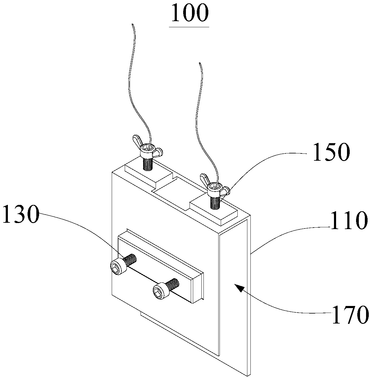
[0034] see figure 1 , this embodiment provides a battery test fixture 100, which is used to clamp and fix the battery to be tested to facilitate subsequent testing. The battery test fixture 100 provided by this embodiment includes a test splint 110, a fastener 130 and a test connector 150. The test clamping plate 110 has a clamping cavity 170 for accommodating the battery to be tested. The fastener 130 is arranged on the testing clamping plate 110 and extends into the clamping cavity 170 for abutting against the battery to be tested. The connecting piece 150 is disposed at the end of the test clamping plate 110 and extends into the clamping cavity 170 for being pressed against the battery to be tested and electrically connected to the battery to be tested.

[0035] It should be noted that, in this embodiment, the casing of the battery to be tested is in the shape of a rectangle, and the shape of the clamping cavity 170 is matched with the battery to ...

Example

[0051] Second Embodiment

[0052] This embodiment provides a battery test tool, including a battery to be tested and a battery test fixture 100, wherein the basic structure, principle and technical effects of the battery test fixture 100 are the same as those of the first embodiment. For brief description, this embodiment For parts not mentioned, reference may be made to the corresponding content in the first embodiment.

[0053] The battery test fixture 100 includes a test clamp plate 110 , a fastener 130 and a test connector 150 , the test clamp plate 110 has a clamping cavity 170 for accommodating a battery to be tested, and the fastener 130 is arranged on the test clamp plate 110 and extends into it The clamping cavity 170 is used to abut against the battery to be tested, and the test connector 150 is disposed at the end of the test clamping plate 110 and extends into the clamping cavity 170 to be used to abut against the battery to be tested and connect with the battery t...


PUM


Abstract

The invention provides a battery test fixture and battery test tooling, and relates to the technical field of battery testing. The battery test fixture comprises a test clamp plate, a fastener and a test connector, the test clamp plate has a clamping cavity for accommodating a battery to be tested, the fastener is disposed on the test clamp plate and extends into the clamping cavity for resistingthe battery to be tested, and the test connector is disposed at the end of the test clamp plate and extends into the clamping cavity for resisting the battery to be tested and being electrically connected to the battery to be tested. Compared with the prior art, the invention provides the battery test fixture capable of being clamped and fixed by the fastener and connected through the test connector, the battery to be tested is tightly connected with a testing wire without using other auxiliary tools, the welding process before each battery to be tested is tested is eliminated, the fixture saves energy, reduces material waste, and improves test efficiency, the battery test fixture can be recycled, and waste of resources is avoided.

Description

technical field [0001] The invention relates to the technical field of battery testing, in particular, to a battery testing fixture and a battery testing tool. Background technique [0002] At this stage, after the lithium battery is assembled, a series of battery electrical performance and safety performance tests are required. During the test process, the battery and the test instrument are required to be closely connected to ensure the accuracy of the battery test. Weld the aluminum bars or other connecting devices, and then tighten the cables on the battery test system with screws to ensure the tight connection between the battery and the test instrument. After the test, the aluminum bars or connecting devices cannot be used again, and each battery needs to be welded. The process is more complicated. [0003] In view of this, it is particularly important to design and manufacture a battery test fixture with a simple structure and convenient operation, which can make the...

Claims


Application Information

Patent Timeline
IPC IPC(8): G01R31/385G01R1/04
CPCG01R1/0408G01R1/0416
Inventor 赖信华李晓昆高峰董锋
Owner 成都市银隆新能源产业技术研究有限公司
Why Eureka
Try Eureka