LED driver

A LED driver, the first technology, applied in the direction of lighting devices, light sources, electrical components, etc., can solve the problems that LED drivers cannot meet the height requirements of flat lamps, lamps lose competitiveness, and the cost of magnetic cores is expensive, etc., to achieve high frequency suppression Electromagnetic noise, meeting height requirements, effect of reducing height

Pending Publication Date: 2019-03-08
NINGBO FAREAST LIGHTING
View PDF0 Cites 2 Cited by
  • Summary
  • Abstract
  • Description
  • Claims
  • Application Information

AI Technical Summary

Problems solved by technology

The height of the energy storage inductor makes the LED driver unable to meet the height requirements of flat lamps
If a custom core size is used, the

Method used


Image

  • LED driver
  • LED driver
  • LED driver

Examples


Example Embodiment

[0021] Example one

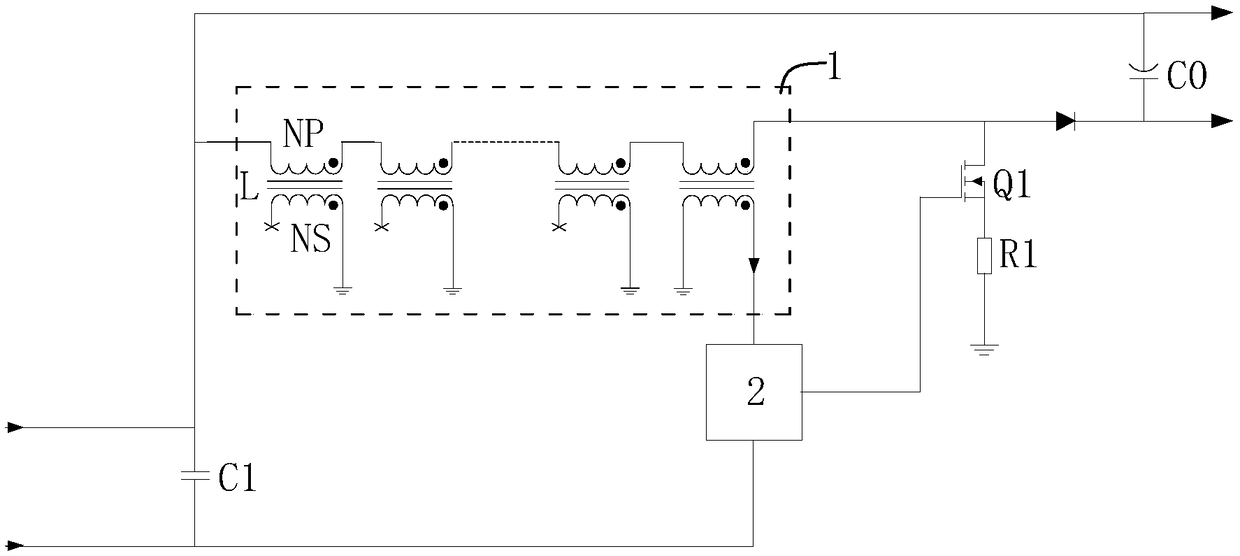
[0022] Such as image 3 As shown, the LED driver in this embodiment includes a first capacitor C1, a second capacitor C0, a transistor Q1, a diode D1, an energy storage inductance unit 1 and a control circuit board 2.

[0023] The two ends of the first capacitor C1 are used as input terminals of the LED driver, the two ends of the first capacitor C1 are respectively electrically connected to the power supply, and the first end of the first capacitor C1 is grounded.

[0024] The two ends of the second capacitor C0 are used as the output ends of the LED driver, and the two ends of the second capacitor C0 are respectively electrically connected to the LED lamp load, thereby supplying power to the LED lamp.

[0025] The source of the transistor Q1 is grounded through the resistor R1, and the drain of the transistor Q1 is electrically connected to the first end of the second capacitor C0 through the diode D1. That is, the drain of the transistor Q1 is electrically conn...

Example Embodiment

[0032] Example two

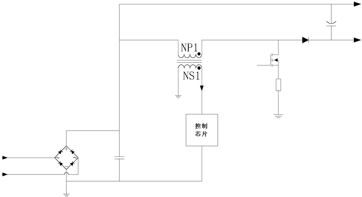
[0033] Such as Figure 4 As shown, the difference between this embodiment and the first embodiment is only: the first power connection end of the control chip is connected to the second end of the first capacitor C1 through a peripheral circuit, and the control chip is directly supplied with power through the power supply. During implementation, Only need to set up the corresponding peripheral circuit.


PUM


Abstract

The invention relates to an LED driver. The LED driver comprises a first capacitor, a second capacitor, a transistor, a diode, an energy storage inductance unit and a control circuit board; two ends of the first capacitors are electrically connected with a power supply, two ends of the second capacitor are electrically connected with the load; a source electrode of the transistor is grounded through a resistor, a drain electrode is electrically connected with the first end of the second capacitor; the energy storage inductance unit comprises at least two energy storage inductors in series connection; a first connecting end of the energy storage induction unit is electrically connected with the second end of the first capacitor and the second end of the second capacitor, and a second connecting end of the energy storage induction unit is electrically connected with the drain electrode of the transistor; a control signal connecting end of the control circuit board is electrically connected with a grid electrode of the transistor. Through the LED driver disclosed by the invention, a magnetic core in each energy storage inductor of the energy storage induction unit is small, and the flattening arrangement can be realized, and then the height of the energy storage inductor can be reduced, and the height requirement of the flattened lamp is satisfied.

Description

technical field [0001] The invention relates to the technical field of LED lamps, and specifically relates to an LED driver. Background technique [0002] At present, LED light sources have been gradually accepted by the lighting market and are constantly replacing traditional light sources. One of the differences between LED light sources and traditional light sources lies in the driving method. LED light sources must be driven by an LED driver to provide a constant DC current to realize the lighting function. In addition, the LED light source is a point light source. In order to realize large-area lighting, it is necessary to use multiple LED light sources to connect in series and parallel, and to achieve uniform surface lighting through the light distribution of the lamps. Therefore, a lamp composed of an LED light source can realize a flat lamp. [0003] However, when designing a flat lamp, because the LED light source needs to be driven by an LED driver, the thickness...

Claims


Application Information

Patent Timeline
IPC IPC(8): H05B33/08H05B44/00
CPCH05B45/00
Inventor 黄敏超
Owner NINGBO FAREAST LIGHTING
Why Eureka
Try Eureka